Common Diagram Elements
Common Diagram Elements are described here.

Icon
Description
Add comments to Model Elements.
Anchor Notes to related Model Elements.


Insert Text / TextBox.

Draw Rectangles/Filled Rectangles in Diagrams.

Draw Rounded Rectangles/Filled Rounded Rectangles in Diagrams.

Draw Ovals/Filled Ovals in Diagrams.
Draw lines on Diagrams.
Draw Freehand lines on Diagrams.
Draw Highlighter on Diagrams.
Insert Images.
Lock the selected mode on the Tool Palette.
Place the ends of lines at the center of Model Elements.
Set the Line Mode (Line, Line (Right Angle), Curve, Curve (Right Angle)) to draw lines between Model Elements.
Switch On/Off the Suggest Feature. The default setting can be set in [System Properties]- Diagram Editor -[Enable Suggest Feature].


Notes and Note Anchors
Notes can be used to add comments to Model Elements. Note Anchors bind Notes to Model Elements.
Press [Enter] to fix the Text in the Note.
To insert a new line in the Note, press [Shift+Enter] or [Alt+Enter].

Show / hide notes
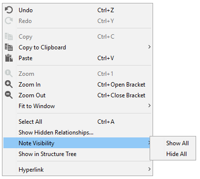
Specify whether to show or hide notes. It is available in SysML diagrams.
From the context menu that opens by right-clicking on the diagram, select [Note Visibility]-[Show All] or [Hide All] to specify whether to show or hide all the notes on the diagram.
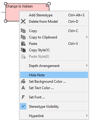
You can also choose to show or hide notes individually by selecting [Hide Note] from the Context Menu of the note.
Text / Textbox
Select
To insert a new line, press [Shift+Enter] or [Alt+Enter].
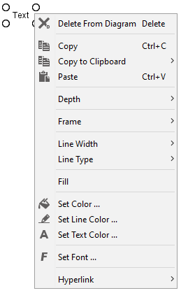
Border, frame width, line type, fill, background color, line color, text color and font can be set from the context menu.
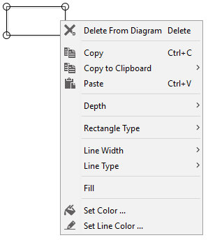
Rectangles/Rounded Rectangles/Ovals
Select
Rectangle Type
Line Width
Line Type
Fill
Background Color
Line Color
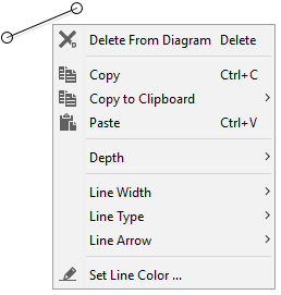
Lines
Select
[[Line] on the Tool Palette and drag the mouse on the Diagram.
Line Width
To change a Line Width, right-click on the target Line and select [Line Width].
Line Type
To change a Line Type, right-click on the target Line and select [Line Type].
Line with Arrow
To change a Line with Arrow, right-click on the target Line and select [Line Arrow].
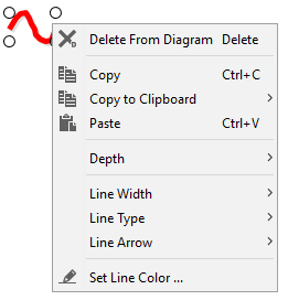
Freehand
Select
[FreeHand] on the Tool Palette and drag the mouse on the Diagram. The line width, line type, line arrow and line color can be set from the context menu.
Highlighter
Select
[Highlighter] on the Tool Palette and drag the mouse on the Diagram. The line width, alpha, line type and line color can be set from the context menu.

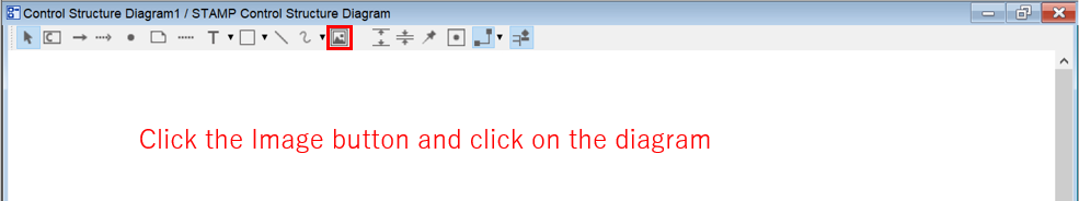
Images
Select
 [Image] on the Tool Palette and click on the Diagram.
Select an Image in the Open dialog and click [Open].
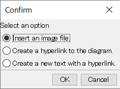
You can also insert an image by dragging and dropping the image file directly onto the diagram.
Drag and drop the image file onto the diagram.
In the dialog that opens, select [Insert an image file] and click [OK].