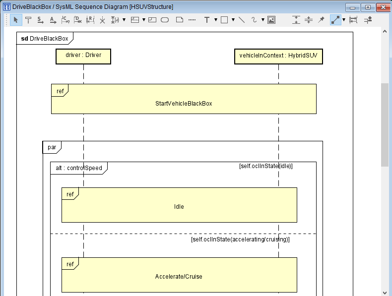
Sequence Diagram
The Sequence Diagram represents the interaction between classes and objects along the time axis.
Creating a Sequence Diagram
Sequence Diagram can be added by the following procedure:
Click [Sequence Diagram] from [Diagram] on the Main Menu.
Use the context menu from [Structure] in [Project View].
Use Edit InteractionUse.
Diagram Elements of Sequence Diagrams

Description of each icon¶ Type
Icon
Description
Select
The basic operations of the Diagram Editor can be executed in this mode.
LifeLine
Add a Lifeline.
Message
Add a Message.
Asynchronous Message
Add an Asynchronous Message.
Create Message
Add a Create Message.
Delete Message
Add a Delete Message.
Reply Message
Add a Reply Message.
Stop
Add a Stop.
Duration Constraint
Add a Duration Constraint.
Time Constraint
Add a Time Constraint. Select from the pull-down of the Duration Constraint icon.
CombinedFragment
Add a CombinedFragment. You can select either of alt, assert, break, consider, critical, ignore, loop, neg, opt, par, seq, or strict from the pull-down.
InteractionUse
Add an InteractionUse.
StateInvariant
Add a StateInvariant.
Refer to Common Diagram Elements for information on other items.

LifeLine
Creating a LifeLine
Lifeline can be created by the following procedure:
Double-click on the Sequence Diagram.
Select [Lifeline]
in the Tool Bar and click on the diagram.
Drag and drop the Block or Actor from the [Structure] to the diagram.

Editing the LifeLine
Visibility of LifeLine Name/Type Name
Set whether to show or hide the LifeLine name/Type name.
Select [Name Visibility] from the context menu.
Select [Type Visibility] from the context menu.
When the name is hidden

Stereotype Visibility …
Set the stereotype visibility of figure elements individually by the following procedure:
Select [Stereotype Visibility …] from the context menu.
Adjust Lifeline Length
Adjust the LifeLine Length by the following procedure:
Drag and drop the end of the LifeLine on the Sequence Diagram.
Select the default length from [Adjust Lifeline Length] in the context menu of the LifeLine.
Select either of [Default]/[Align to Minimum]/[Align to Maximum] from [Adjust Lifeline Length] in the context menu of the Sequence Diagram.
Adjust ExecutionSpecification Length
Adjust the ExecutionSpecification Length by the following procedure:
Drag and drop the end of the Execution Specification View on the Sequence Diagram.
Select the default length from [Adjust ExecutionSpecification Length] in the context menu of the Execution Specification View.
Select the default length from [Adjust ExecutionSpecification Length] in the context menu of the Sequence Diagram.
Synchronous Message
Creating a Synchronous Message
Synchronous Message can be created by the following procedure:
Using the Tool Bar
Select [Message]
in the Tool Bar.
Click the LifeLine that sends the message.
Click the LifeLine that receives the message.
Using the Draw Suggest
Select [Synchronous Message] in the Draw Suggest.

Editing the Synchronous Message
Editign the Synchronous Message Name
Synchronous Message name can be edited by the following procedure:
Double-click the name of the Diagram Element on the Diagram Editor and edit the name.
Edit from the [Base] tab in the Property View.
Message Parameter/ Parameter Type/Parameter Direction Kind Visibility
Select each visibility from [Message Parameter Visibility], [Message Parameter Type Visibility], or [Message Parameter Direction Kind Visibility].
Adding a Stereotype
Stereotype can be added by the following procedure:
Select [Add Stereotype] from the context menu.
Add a stereotype from the [Stereotype] tab of the Property View.
Adding a Constraint
Constraint can be added by the following procedure:
Select [Add Constraint] from the context menu.
Add a Constraint from the [Constraint] tab of the Property View.
Constraint Visibility
Constraint visibility can be selected by the following procedure:
Select [Constraint Visibility] from the context menu.
Changing the Source/Target of the Synchronous Message
Drag and drop the Execution Specification View that sends or receives the Synchronous Message to another LifeLine to change the LifeLine that sends or receives the Synchronous Message. (There are some restrictions.)
Asynchronous Message
Creating an Asynchronous Message
Asynchronous Message can be created by the following procedure:
Using the Tool Bar
Select [Asynchronous Message]
in the Tool Bar.
Click the LifeLine that sends the message.
Click the LifeLine that receives the message.
Using the Draw Suggest
Select [Asynchronous Message] in the Draw Suggest.

Editing the Asynchronous Message
Refer to Edit Synchronous Message Name for details.
Found Message
Creating a Found Message
Found Message can be created by the following procedure:
Select [Message]
Click other than the LifeLine and the LifeLine to receive the message in order.

Lost Message
Creating a Lost Message
Lost Message can be created by the following procedure:
Select [Message]
Click the Lifeline that sends the message and other than the LifeLine in order.

Gate
Creating a Gate
Gate can be created by the following procedure:
Select [Message]
Click the Frame and the LifeLine to receive the message in order.

Create Message
Creating a Create Message
Create Message can be created by the following procedure:
Select [Create Message]
in the Tool Bar.
Click the Lifeline that sends the message and the LifeLine that receive the message in order.

Editing the Create Message
Refer to Edit Synchronous Message Name for details.
Delete Message
Creating a Delete Message
Delete Message can be created by the following procedure:
Select [Delete Message]
in the Tool Bar.
Click the Lifeline that sends the message and the LifeLine that receive the message in order.

Editing the Delete Message
Refer to Edit Synchronous Message Name for details.
Reply Message
Creating a Reply Message
Reply Message can be created by the following procedure: Set the Execution Specification Visibility of the Base tab in the Property View to ON when the Execution Specification View is hidden.
Select [Reply Message]
in the Tool Bar and click the Execution Specification View of the message that sends the Reply Message.

Note
Or, create a Reply Message while “Create Reply Message” of the message context menu or [Turn this on if you want to auto-create Reply Messages.]
of the Tool Bar is set to on.
Editing the Reply Message
Refer to Edit Synchronous Message Name for details.
Stop
Creating a Stop
Stop can be created by the following procedure:
Select [Stop]
in the Tool Bar and click the LifeLine to set the Stop.

Duration Constraint
Creating a Duration Constraint
Duration Constraint can be created by the following procedure:
Select [Duration Constraint]
in the Tool Bar.
Click the message to set at the beginning of the Duration Constraint, then click the message to set at the end.

Specify the time duration.

Time Constraint
Creating a Time Constraint
Time Constraint can be created by the following procedure:
Select [Time Constraint]
in the Tool Bar.
Click the message to create the Time Constraint.

Specify the time duration.

CombinedFragment
Creating a CombinedFragment
CombinedFragment can be created by the following procedure:
Select [CombinedFragment ]
in the Tool Bar and drag it over the LifeLine that the CombinedFragment is to be set.

Editing the CombinedFragment
Editing the CombinedFragment Name
CombinedFragment name can be edited by the following procedure:
Place the cursor on “alt” on the upper left of the CombinedFragment and double-click to edit it.
Edit from the [Base] tab in the Property View.
Adding an Operand
Click [Add Operand] in the context menu and double-click [Guard] of the entered Operand to edit the Guard.
Add from the [Operand] tab of the Property View.

InteractionUse
Creating an InteractionUse
InteractionUse can be created by the following procedure:
Select [InteractionUse ]
in the Tool Bar and drag it over the LifeLine that the InteractionUse is to be set.

Editing the InteractionUse
Editing the InteractionUse Name
InteractionUse name can be edited by the following procedure:
Double-click the name of the Diagram Element on the Diagram Editor and edit the name.
Edit from the [Base] tab in the Property View.
Select the visibility setting of the LifeLine name from [Name Visibility] in the context menu.
Creating a Sequence Diagram
Create a Sequence Diagram from the InteractionUse by the following procedure:
Right-click the InteractionUse with no associated Sequence Diagram set and select [Create Sequence Diagram] from the context menu.
Double-click the InteractionUse with no associated Sequence Diagram set.
Opening the Associated Sequence Diagram
Sequence Diagram can open by the following procedure:
Right-click the InteractionUse with the associated Sequence Diagram set and select [Open Diagram] from the context menu.
Double-click the InteractionUse with the associated Sequence Diagram set.

