System Properties
The System Properties of SysML can be set up by selecting [Tools]-[System Properties] in the Main Menu to open [SysML].
To apply settings to the current project, check on “Apply the project settings to the current project” in the System Property dialog.
Project View
Set the properties related to the Project View.
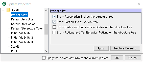
Show Association End on the structure treeDefault [ON]
Show Port on the structure treeDefault [ON]
Show States and Submachine States on the structure treeDefault [OFF]
Show Actions and CallBehavior Actions on the structure treeDefault [OFF]
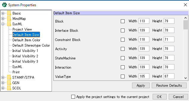
Default Item Size
The initial item size for each model elements can be set in this segment.
To apply the size you input, please check the box. All check boxes are [OFF] by default.
Some models may appear in different size despite the size you specify depending on the length of its name, etc.
Default size should be from 1 to 1000.
No.
Model
Width
Height
1
Block
113
79
2
Interface Block
139
78
3
Constraint Block
118
71
4
Activity
139
78
5
StateMachine
139
78
6
Interaction
139
78
7
Value Type
105
87
8
Enumeration
105
87
9
Unit
68
39
10
QuantityKind
115
39
11
Constraint Property
187
40
12
Value Property
93
36
13
Interface
20
35
14
Package
70
73
15
Model
73
73
16
Partition - [Activity]
175
495
17
Action
87
24
18
SendSignalAction
158
39
19
AcceptEventAction
150
39
20
CallBehaviorAction
130
31
21
InitialNode - [Activity]
20
20
22
ActivityFinal - [Activity]
20
20
23
Decision Node & Merge Node - [Activity]
30
20
24
ObjectNode
62
17
25
ActivityParameterNode
62
17
26
Actor
40
70
27
UseCase
140
40
28
InitialPseudostate - [Statemachine]
20
20
29
State
55
50
30
FinalState - [Statemachine]
20
20
31
ShallowHistoryPseudostate
20
20
32
DeepHistoryPseudostate
20
20
33
JunctionPseudostate
15
15
34
ChoicePseudostate
15
15
35
SubmachineState
150
60
36
LifeLine
110
30
37
StateInvariant
60
36
38
Part
136
35
39
Requirement
115
77
40
TestCase
105
68
41
Frame
640
480
42
Note
150
60
Default Item Color
Set the color when creating new Diagram Elements.
※ Project icon displayed at the top of each model
When the project icon is displayed for certain Diagram Elements, the color settings for those elements are saved to each project that is created.
To sync the settings of the project with the settings in the System Properties, click [Project Settings] in the project properties.

Default [Eggshell]
No.
Button name
Description
1
Eggshell
Preset 1 (Eggshell) is set for new Diagram Elements. (Default)
2
Blue
Preset 2 (Blue) is set for new Diagram Elements.
3
No Fill
New Diagram Elements are in no color.
Click the settings box of the Diagram Element for which to set the color.
Select or create a color and click [OK] in the Color Selection dialog.
The color specified in the System Properties is applied when adding new Diagram Elements.
Default Stereotype Color
The initial color for each Stereotype can be set in this segment. Colors can be set for up to 9 Stereotypes.
- ※ Project icon displayed at the top of each model
When the project icon is displayed for certain Diagram Elements, the color settings for those elements are saved to each project that is created.
To sync the settings of the project with the settings in the System Properties, click [Project Settings] in the Property View of the project.

- Default
Stereotype 1 - actor
Stereotype 2 - interface
Default [Eggshell]
No.
Button name
Description
1
Eggshell
Preset 1 (Eggshell) is set for new Diagram Elements. (Default)
2
Blue
Preset 2 (Blue) is set for new Diagram Elements.
3
No Fill
New Diagram Elements are in no color.
Click the settings box of the Stereotype for which to set the color.
Select or create a color and click [OK] in the Color Selection dialog.
The color specified in the System Properties is applied when adding new Stereotypes.
Initial Visibility 1
Set whether to show or hide items. The value in the Property View [Initial Visibility] tab of the Block Definition Diagram is used when creating a Block Definition Diagram or Internal Block Diagram.

-
Setting Visibility of Diagram Element Interface Attribute Compartment
Default [ON]
Attribute(Property) Type
Default [ON]
Attribute(Property) Initial Value
Default [ON]
Attribute(Property) Unit
Default [OFF]
Attribute(Property) Stereotype
Default [ON]
Attribute(Property) Constraint
Default [ON]
Interface Operation Compartment
Default [ON]
Operation Return Type
Default [ON]
Operation Parameter
Default [ON]
Operation Parameter Type
Default [ON]
Operation Parameter Direction Kind
Default [OFF]
Operation Stereotype
Default [ON]
Operation Constraint
Default [ON]
Association Name
Default [ON]
Association Name Direction
Default [ON]
Association Constraint
Default [ON]
Association Stereotype
Default [ON]
Dependency Name
Default [ON]
Dependency Constraint
Default [ON]
Dependency Stereotype
Default [ON]
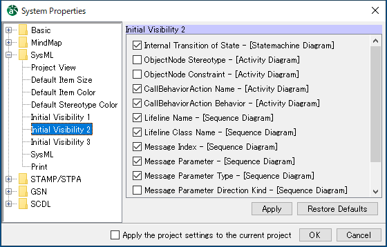
Initial Visibility 2
Set whether to show or hide items. The set value is used as the initial value in the each diagram when creating a Sequence Diagram, Statemachine Diagram, or Activity Diagram.
Setting Visibility of Diagram Element
Internal Transition of State - [Statemachine Diagram]
Default [ON]
Always Display Partition Names - [Activity Diagram]
Default [OFF]
ObjectNode Stereotype - [Activity Diagram]
Default [OFF]
ObjectNode Constraint - [Activity Diagram]
Default [OFF]
CallBehaviorAction Name - [Activity Diagram]
Default [ON]
CallBehaviorAction Behavior - [Activity Diagram]
Default [ON]
Lifeline Name - [Sequence Diagram]
Default [ON]
Lifeline Class Name - [Sequence Diagram]
Default [ON]
Message Index - [Sequence Diagram]
Default [ON]
Message Parameter - [Sequence Diagram]
Default [ON]
Message Parameter Type - [Sequence Diagram]
Default [ON]
Message Parameter Direction Kind - [Sequence Diagram]
Default [OFF]
Message Stereotype - [Sequence Diagram]
Default [ON]
Message Constraint - [Sequence Diagram]
Default [ON]
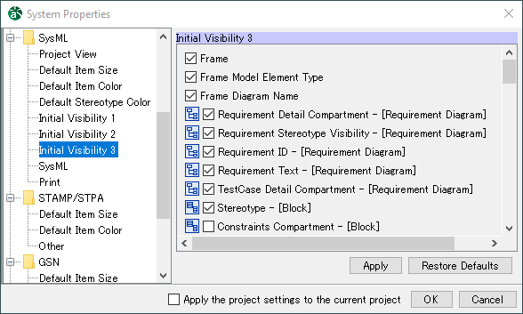
Initial Visibility 3
Set whether to show or hide items. The set value is used in the Property View [Initial Visibility] tab of the each diagram when creating a Requirement Diagram, Block Definition Diagram, Internal Block Diagram, or Parametric Diagram.
Setting Visibility of Diagram Element
Frame
Default [ON]
Frame Model Element Type
Default [ON]
Frame Diagram Name
Default [ON]
Requirement Detail Compartment - [Requirement Diagram]
Default [ON]
Requirement Stereotype Visibility - [Requirement Diagram]
Default [ON]
Requirement ID- [Requirement Diagram]
Default [ON]
Requirement Text - [Requirement Diagram]
Default [ON]
TestCase Detail Compartment - [Requirement Diagram]
Default [ON]
Stereotype - [Block]
Default [ON]
Tagged Value - [Block]
Default [OFF]
Constraints Compartment - [Block]
Default [OFF]
Operation Compartment - [Block]
Default [OFF]
Flowproperties Compartment - [Block]
Default [OFF]
Parts Compartment - [Block]
Default [OFF]
References Compartment - [Block]
Default [OFF]
Values Compartment - [Block]
Default [OFF]
Ports Compartment - [Block]
Default [OFF]
Proxy Ports Compartment - [Block]
Default [OFF]
Full Ports Compartment - [Block]
Default [OFF]
Stereotype - [Interface Block]
Default [ON]
Tagged Value - [Interface Block]
Default [OFF]
Constraints Compartment - [Interface Block]
Default [OFF]
Operations Compartment - [Interface Block]
Default [OFF]
Flowproperties Compartment - [Interface Block]
Default [OFF]
References Compartment - [Interface Block]
Default [OFF]
Ports Compartment - [Interface Block]
Default [OFF]
Proxy Ports Compartment - [Interface Block]
Default [OFF]
Full Ports Compartment - [Interface Block]
Default [OFF]
Stereotype - [Constraint Block]
Default [ON]
Tagged Value - [Constraint Block]
Default [OFF]
Constraints Compartment - [Constraint Block]
Default [OFF]
Constraint Block Parameters Compartment - [Constraint Block]
Default [OFF]
Stereotype - [Value Type]
Default [ON]
Tagged Value - [[Value Type]
Default [OFF]
Operations Compartment - [Value Type]
Default [OFF]
Properties Compartment - [Value Type]
Default [OFF]
Value Type Compartment - [Value Type]
Default [OFF]
Stereotype - [Enumeration]
Default [ON]
Tagged Value - [Enumeration]
Default [OFF]
Operations Compartment - [Enumeration]
Default [OFF]
Properties Compartment - [Enumeration]
Default [OFF]
Enumeration Literals Compartment - [Enumeration]
Default [ON]
Value Type Compartment - [Enumeration]
Default [OFF]
Unit Stereotype - [Block Definition Diagram]
Default [ON]
Unit Name - [Block Definition Diagram]
Default [ON]
Unit Type Name - [Block Definition Diagram]
Default [ON]
Unit Slot - [Block Definition Diagram]
Default [ON]
Unit Slot Value - [Block Definition Diagram]
Default [ON]
Unit Slot without Value - [Block Definition Diagram]
Default [ON]
QuantityKind Stereotype - [Block Definition Diagram]
Default [ON]
QuantityKind Name - [Block Definition Diagram]
Default [ON]
QuantityKind Type Name - [Block Definition Diagram]
Default [ON]
QuantityKind Slot - [Block Definition Diagram]
Default [ON]
QuantityKind Slot Value - [Block Definition Diagram]
Default [ON]
QuantityKind Slot without Value - [Block Definition Diagram]
Default [ON]
Part Stereotype - [Internal Block Diagram]
Default [ON]
Part Name - [Internal Block Diagram]
Default [ON]
Part Type - [Internal Block Diagram]
Default [ON]
Part Multiplicity - [Internal Block Diagram]
Default [ON]
Port Stereotype - [Block Definition Diagram, Internal Block Diagram]
Default [ON]
Port Name - [Block Definition Diagram, Internal Block Diagram]
Default [ON]
Port Type - [Block Definition Diagram, Internal Block Diagram]
Default [ON]
Port Multiplicity - [Block Definition Diagram, Internal Block Diagram]
Default [ON]
Connector Name - [Internal Block Diagram]
Default [ON]
Connector Name Direction - [Internal Block Diagram]
Default [OFF]
Constraint Property Name - [Parametric Diagram]
Default [ON]
Constraint Property Type - [Parametric Diagram]
Default [ON]
Constraint Property Constraints - [Parametric Diagram]
Default [ON]
Constraint Parameter Name - [Parametric Diagram]
Default [ON]
Constraint Parameter Type - [Parametric Diagram]
Default [ON]
Constraint Parameter Multiplicity - [Parametric Diagram]
Default [ON]
Value Property Name - [Parametric Diagram]
Default [ON]
Value Property Type - [Parametric Diagram]
Default [ON]
Value Property initial value - [Parametric Diagram]
Default [ON]
Biding Connector Name - [Parametric Diagram]
Default [ON]
Biding Connector Name Direction - [Parametric Diagram]
Default [OFF]
SysML
Set the properties related to SysML.

Default Type of the Flow Property (Example: SysML::Libraries::PrimitiveValueTypes::Real)Enter the type when creating the Flow Property in the text box.
Default [SysML::Libraries::PrimitiveValueTypes::Real]
Default type of the value (Example: SysML::Libraries::PrimitiveValueTypes::Real)Enter the default type when creating the Value in the text box.
Default [SysML::Libraries::PrimitiveValueTypes::Real]
Default Type of the Property (Example: SysML::Libraries::PrimitiveValueTypes::Real)Enter the default type when creating the Property in the text box.
Default [SysML::Libraries::PrimitiveValueTypes::Real]
Default type of the Constraint Parameter (Example: SysML::Libraries::PrimitiveValueTypes::Real)Enter the default type when creating the Constraint Parameter in the text box.
Default [SysML::Libraries::PrimitiveValueTypes::Real]
Show Control Flow with dashed line in Activity DiagramDefault [OFF]
Print
Set the properties related to the Print.
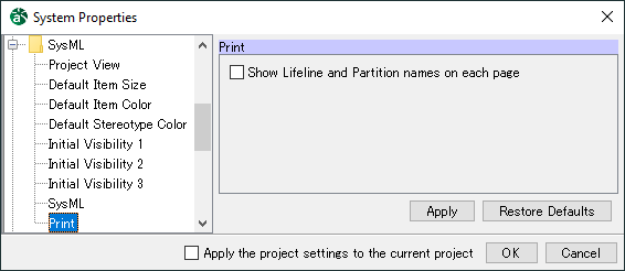
Show Lifeline and Partition names on each pageDefault [OFF]