Editing Diagrams
This chapter describes the Diagram Editor that is used to edit Diagrams.

Diagram Editor Context Menu
You can close other tabs, delete diagrams and print diagams from Diagram editor’s context menu:

Draw Suggest Feature
Draw Suggest Feature appears when you have a mouse over a Model Element in the diagram, providing with a set of suggested Model Elements to help you with modeling faster.
To switch On/Off ![]() the Draw Suggest Feature, click image [Enable Suggest Feature] on the Tool Palette.
the Draw Suggest Feature, click image [Enable Suggest Feature] on the Tool Palette.
While you hold [Shift] key down, setting is toggled another one.
The default setting can be done in Menu [Tools]-[System Properties]-[Diagram Editor]-[Enable Suggest Feature] on the Diagram Editor.
Creating Diagram Elements
Using the Tool Palette
Select the target Diagram Element on the Tool Palette in the Diagram Editor.
Click on the Diagram to create the Diagram Element.
The new Diagram Element is added to the structure tree.
Note) Lines are not added to the structure tree.
Dragging and dropping from the [Structure] onto a Diagram
Drag a Diagram Element from the [Structure] in the Project View.
Drop it onto a Diagram in the Diagram Editor to create the Diagram Element.

Dragging and dropping from the [Search] onto a Diagram
Drag a Diagram Element from the [Search] in the Project View.
Drop it onto a Diagram in the Diagram Editor to create the Diagram Element.
Double-clicking on the Diagram Editor
Double-click on the Diagram Editor to create a main Diagram Element of the Diagram.
Diagram
Main Diagram Element
Requirement Diagram
Requirement
Block Definition Diagram
Block
Internal Block Diagram
Part Property
Parametric Diagram
Constraint Property
Usecase Diagram
Usecase
Activitiy Diagram
Action
Statemachine Diagram
State
Sequence Diagram
Lifeline
Safety Concept Diagram
Requirement
Control Structure Diagram
Component
Control Loop Diagram
Component
GSN / D-Case
Goal
Mindmap
Floating Topic
Using the Draw Suggest Feature
Mouse-over a target Diagram Element.
The Draw Suggest icon is hovered.
Select the icon of the Diagram to create the Diagram Element.


Creating Diagram Elements in Succession
Using [Lock Selected Mode] in the Tool Palette.
Click on the
[Lock Selected Mode] in the Tool Palette.
Select the target Diagram Element.
Click on the Diagram repeatedly.
Using the [Shift] Key
Select the target Diagram Element on the Tool Palette in the Diagram Editor.
Hold down the [Shift] Key and click on the Diagram repeatedly.
Gap Remover/Expander
By the [Gap Remover/Expander] function, multiple Diagram Elements can be moved at the same time.You can create a space for another Diagram Element on the Diagram later or improve the appearance of the Diagram.It can be used other than the Mindmap.
Click
[Gap Expander] or
[Gap Remover] on the Tool Palette to turn the Gap Remover/Expander mode ON.
Click on the point to expand or to remove on the Diagram and drag it.
Editing Diagram Elements
Editing Names
Double-click the name of the Diagram Element and edit the name.

Note) You can edit the name in the [Structure] of the [Project View] or in the [Property View].
Resizing
Auto Resize
A Diagram element is resized automatically according to the changed name.
Manual Resize
Click the target Diagram Element and drag the corner.
Customized Icons
Setting Customized Icon for Stereotype
Follow the steps below to set the Customized Icon for the Stereotype.
Select the Project in the Structure Tree.
Go down to its Property View, and then select the Stereotype and click
in the [Profile Stereotype] tab.
In the [Edit Stereotype Definition] dialog, set the [Icon] to an image.
Gif, jpeg, jpg, png formats are supported.


Switch notation of Diagram Element
Follow the steps below to switch the notation of the Diagram Element to the Customized Icon notation.
Appley the Stereotype with the Customized Icon set to the Model Element of the Diagram Element.
Select the Diagram Element in the Diagram Editor and click the triangle on the
button on the Tool Bar.
Click
button.

Note
Please refer to SysML Related Functions - Profile for details.
Multiple Selection/Cancel
Multiple Selection
Dragging
Drag the cursor over the Diagram Editor to select the target Diagram Elements.
Using the [Shift] or [Ctrl] Key
Select the Diagram Elements in the Diagram Editor by holding down the [Shift] or [Ctrl] key.
Note
Selecting all Diagram Elements in a Diagram
To select all Diagram elements on the Diagram, click [Select All] from [Edit] in the Main Menu or from the Context Menu in the Diagram Editor.
[Ctrl+A], the short cut key for [Select All] is also available.
Canceling the Selection
To cancel a selection, hold down the [Shift] or [Ctrl] key and reselect the selected Diagram Elements.
Copying as Images
Diagram Elements copied by [Copy to Clipboard] are stored in the Clipboard and can be pasted into other applications (MS Word, etc) as images or EMFs (Enhanced Meta File).This function is not available in Astah for Mac.
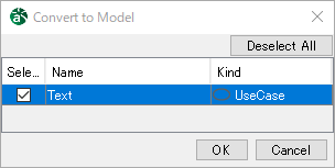
Pasting Text from Clipboard
Copy the text to the clipboard and paste it on the Diagram in the Diagram Editor to display the model conversion dialog.
Select a type and create a Diagram Element.
Color Setup
Setting up Colors of Diagram Elements
Using [Edit] in the Main Menu
Select the target Diagram Element(s) in the Diagram Editor.
Select [Edit] - [Set Color] in the Main Menu.
Select or create a color and click [OK] in the color selection dialog.
Using the Tool Bar in the [Management View]
Select the target Diagram Elements in the Diagram Editor.
Click the triangle on the [Set Color] button on the Tool Bar.
Select or create a color in the color selection dialog.
When clicking the color on the [Set Color] button on the Tool Bar, set the previously used color.
Using the Context Menu
Click [Set Color] from the context menu of the Diagram Element.
Select or create a color and click [OK] in the color selection dialog.
Color Selection Dialog
The color selection dialog contains six image color groups: Aqua, Earth, Nature, Spring, Passion, and Winter.
Use the groups to create well-balanced color.
Press the [Add Color] button to memorize up to 10 colors in [Favorites].

Setting up Text Colors
Using [Edit] in the Main Menu
Select the target Diagram Elements in the Diagram Editor.
Select [Edit] - [Set Text Color] in the Main Menu.
Select or create a color and click [OK] in the color selection dialog.
Using the Tool Bar in the [Management View]
Select string(s) of the target Diagram Elements in the Diagram Editor.
When clicking the triangle on the [Set Text Color] button on the Tool Bar, select or create a color in the color selection dialog.
When clicking the color on the [Set Text Color] button on the Tool Bar, set the previously used color.
Using the Context Menu
Click [Set Text Color] from the context menu of the Diagram Element.
Select or create a color and click [OK] in the color selection dialog.
Set Style
The context menu of each diagram element allows you to set the color, line color, text color, font, line style, and other styles.
The styles that can be set vary depending on the diagram element.
Editing Lines
Creating Lines
There are four line styles: Line, Line (Right Angle), Curve, and Curve (Right Angle).
By default, Line (Right Angle) is used for all Diagrams.
Note) To cancel drawing a line, press the [Esc] key or right-click.
Creating Line, Line(Right Angle), Curve, and Curve (Right Angle)
Select the target line type from the Tool Palette in the Diagram Editor.
Select [Line], [Line(Right Angle)], [Curve], or [Curve (Right Angle)] in the Tool Palette.
Click on the Diagram Element to select the starting point of the line and the second one to select the end point.
Note 1) To draw a polygonal line, click on a Diagram Element and click on any point on the Diagram. Finally, click on a Diagram Element to select the end point.
Editing Targets of Lines
To change the end point of a Line, simply drag the end point onto a new target.
Editing Line Styles
There are four line styles: Line, Line (Right Angle), Curve, and Curve (Right Angle).
Using [Edit] in the Main Menu
Select a Line in the Diagram Editor.
Click [Edit] - [Line style] and select one of the line styles.
Using buttons on the Tool Bar
Select a Line in the Diagram Editor.
Click one of the line styles on the Tool Bar in the Management View.

Using the Context Menu
Select one of the line styles from [Line style] in the context menu in the Diagram Editor.
Note
To Set Default Line Style
Set the line mode on the Tool Bar in the Diagram Editor. Existing Lines are not changed to the selected line mode.

Setting up Line Color
Using [Edit] in the Main Menu
Select the target line(s) in the Diagram Editor.
Click [Edit] - [Set Line Color] in the Main Menu.
Select or create a color and click [OK] in the color selection dialog.
Using the Tool Bar in the [Management View]
Select the target line(s) in the Diagram Editor.
When clicking the triangle on the [Set Line Color] button on the Tool Bar, select or create a color in the color selection dialog.
When clicking the color on the [Set Line Color] button on the Tool Bar, set the previously used color.
Using the Context Menu
Select [Set Line Color] in the context menu of the target line in the Diagram Editor.
Select or create a color and click [OK] in the color selection dialog.
Displaying Diagrams
Enlarging Diagrams
Click [View] - [Zoom In] in the Main Menu. (Ctrl+ [)
Click [Zoom In] on the Tool Bar.
Using the Context Menu
Right-click on the Diagram Editor to open the context menu.
Click [Zoom In] on the context menu.
Using the [Ctrl] key and the mouse
Hold down the [Ctrl] key and right mouse button and drag upwards.
Hold down the [Ctrl] key and rotate the mouse wheel forwards.
Shrinking Diagrams
Click [View] - [Zoom Out] in the Main Menu. (Ctrl+ ])
Click [Zoom Out] on the Tool Bar.
Using the Context Menu
Right-click on the Diagram Editor to open the context menu.
Click [Zoom Out] on the context menu.
Using the [Ctrl] key and the mouse
Hold down the [Ctrl] key and right mouse button and drag downwards.
Hold down the [Ctrl] key and rotate the mouse wheel backwards.
Displaying Diagrams in their Original Size
Click [View] - [Actual Size] in the Main Menu.
Click [Actual Size] on the Tool Bar.
Using the Context Menu
Right-click on the Diagram Editor to open the context menu.
Click [Normal] on the context menu.
Displaying the Diagram Overview
[Fit to Window], [Window Width], and [Window Height] can be selected.
Click [View]-[Fit to Window/Window Width/Window Height] in the Main Menu.
Click [Fit to Window/Window Width/Window Height] on the Tool Bar.
Using the Context Menu
Right-click on the Diagram Editor to open the context menu.
Click [View]-[Fit to Window/Window Width/Window Height] on the context menu.
Note) [Map] in the Project View can be used to enlarge and shrink Diagrams.
Moving Diagrams
While pressing the right mouse button, drag Diagrams to move in the Diagram Editor.
Moving Diagrams Vertically
Diagrams can be moved vertically by rotating the mouse wheel. When the mouse wheel is rotated forwards, Diagrams are moved upwards. When the mouse wheel is rotated backwards, Diagrams are moved downwards.
Moving Diagrams Horizontally
Diagrams can be moved horizontally by holding down the [Shift] key and rotating the mouse wheel. When the mouse wheel is rotated forwards, Diagrams are moved to the right. When the mouse wheel is rotated backwards, Diagrams are moved to the left.
Alignment of Diagram Elements
Adjust Top
Align the selected Diagram Elements with the top end of the highest Diagram Element.
Align Horizontal Center
Align the Diagram Elements along the midpoint between the highest and lowest Diagram Elements.
Adjust Bottom
Align the selected Diagram Elements with the bottom end of the lowest Diagram Element.
Space Evenly Horizontally
Horizontally align Diagram Elements with even spacing between the leftmost and rightmost Diagram Elements.
Adjust Left
Align Diagram Elements with the left side of the leftmost Diagram Element.
Align Vertical Center
Align Diagram Elements along the midpoint between the leftmost and rightmost Diagram Elements.
Adjust Right
Align Diagram Elements with the right side of the rightmost Diagram Element.
Space Evenly Vertically
Vertically align Diagram Elements with even spacing between the highest and lowest Diagram Elements.
Adjust Width
Adjust the width of Diagram Elements to the widest Diagram Element.
Adjust Height
Adjust the height of Diagram Elements to the highest Diagram Element.
Adjust Size
The size of the Diagram Elements can be adjusted to the selected Diagram Element or the specified width and height.
Using the Tool Button
Select the target Diagram Elements and click one of the Alignment buttons from the Tool buttons.
Using [Align] on the Menu
Select the target Diagram Elements and select one of the options from [Alignment] in the Main Menu.
Adjusting Size
The size of the Diagram Elements can be adjusted to the selected Diagram Element or the specified width and height.

Select the target Diagram Elements.
Select [Alignment] - [Adjust Size] - [Adjust Size] in the Main Menu.
Adjust size
Select [Adjust size] to input the width and height values and press [OK].
Adjust to the size of selected element
Select [Adjust to the size of selected element]. Select the Diagram Element of the target size from the list and press [OK]. Some of the Diagram Elements may not be adjusted properly depending on the length of the name and so on.
Align Guide
The Align Guide (green line) appears on the Diagram Editor when moving the Diagram Elements. This function helps to align the Diagram Elements to other Diagram Elements.

Jumping to Models in the Structure Tree
Click [Show in Structure Tree] from the context menu of the Diagram Element in the Diagram Editor.
Show in Structure Tree from the Editor
Click on the Diagram to open the context menu and click [Show in Structure Tree].
Changing the order of overlapped Model Elements
[Bring to Front]
Move the selected Diagram Element to the top.
[Bring Forward]
Move the selected Diagram Element one step closer to the front
[Send Backward]
Move the selected Diagram Element one step back.
[Send to Back]
Send the selected Diagram Element to the back of all the Diagram Elements.
Using the Tool ButtonSelect the target Diagram Element(s) and click one of the
buttons from the Tool buttons.
Using [Depth Arrangement] in the Main MenuSelect the Diagram Element(s) and select the way you would like to move it from [Edit]-[Depth Arrangement] in the Main Menu.
iii) Using the Context Menu
Select the Diagram Element(s) to open the context menu.
Click the way you would like to move it in [Depth Arrangement] of the context menu.
Search for Diagram Elements
Use the Search Bar or Search View to search for the Diagram elements.
Using the Search Bar
Display the Search Bar on the Diagram Editor by either of the following procedure:
Press the shortcut key [Ctrl+F] in the Diagram Editor.
Select [Search on Diagram] from [Edit] in the Main Menu.
Enter a search text and follow either of the procedure below:
Press the Enter key.
Press the [Next] or [Previous] button.
The searched text is highlighted on the Diagram.
If multiple texts are searched, press [Next] or [Previous] to see the next.
The search setting can be changed in the [Options] button.

Using the Search ViewRefer to Basic Function - Project View - Search View for details.
Switching between editors
You can also use shortcut keys to switch between tabs in the diagram editor.
The following four shortcut keys can be used to switch between editors: Command key instead of Ctrl for Mac OS.
Shortcut Keys
Function
Ctrl + PgDn
Forward to next editor
Ctrl + PgUp
Back to previous editor
Control+TAB
Forward to next editor
Control+Shift+TAB
Back to previous editor
Map View
The lower right corner of the diagram editor shows the entire map of the diagram open in the diagram editor.
The area displayed in the Diagram Editor can be specified by a right-drag. The Diagram in the Diagram Editor can be scrolled using a left-drag. This function is especially useful for big Diagrams that do not fit in the screen.

Resize Map View
You can resize the Map View by dragging and dropping the corners of the map view.

Displaying Map View
Close Map View by clicking the
.
Click the
to reopen MapView.