Activity Diagram
The Activity Diagram represents the sequential steps as things progress, such as the processing flow of business and programs.

Creating an Activity Diagram
Activity Diagram can be added by the following procedure:
Click [Activity Diagram] from [Diagram] on the Main Menu.
Use the context menu from [Structure] in [Project View].
Diagram Elements of the Activity Diagram

Description of each icon¶ Type
Icon
Description
Select
The basic operations of the Diagram Editor can be executed in this mode.
Partition [Vertical]
Add a Partition [Vertical].
Partition [Horizontal]
Add a Partition [Horizontal]
Initial Node
Add an Initial Node.
Action
Add an Action.
CallBehaviorAction
Add a CallBehaviorAction.
Activity Final
Add an Activity Final.
Flow Final Node
Add a Flow Final Node.
ControlFlow
Add a ControlFlow.
ObjectFlow
Add a ObjectFlow.
DecisionNode
Add a DecisionNode.
Merge Node
Add a Merge Node.
Fork Node
Add a Fork Node.
Fork Node
Add a landscape Fork Node. Select from the pull-down of the Fork Node icon.
JoinNode
Add a JoinNode.
JoinNode
Add a landscape JoinNode. Select from the pull-down of the JoinNode icon.
InputPin
Add an InputPin.
OutputPin
Add an OutputPin.
ObjectNode
Add an ObjectNode.
Activity ParameterNode
Add an Activity ParameterNode.
SendSignalAction
Add a SendSignalAction.
AcceptEventAction
Add an AcceptEventAction. Select from the pull-down of the AcceptSignalAction.
AcceptTimeEventAction
Add an AcceptTimeEventAction. Select from the pull-down of the AcceptSignalAction.
Dependency
Add a Dependency.
Refer to Common Diagram Elements for information on other items.

Partition
Creating a Partition [Vertical]
Partition [Vertical] can be created by the following procedure:
Select [Partition [Vertical] ]
in the Tool Bar and click on the diagram.

Creating a Partition [Horizontal]
Partition [Horizontal] can be created by the following procedure:
Select [Partition [Horizontal] ]
in the Tool Bar and click on the diagram.

Editing the Partition
Editing the Name
Name can be edited by the following procedure:
Double-click the name of the diagram element on the Diagram Editor and edit the name.
Edit from the [Base] tab in the Property View.

Creating a Parent Partition
Parent Partition can be created by the following procedure:
Select [Create Parent Partition] from the context menu.

Stereotype Visibility …
Sets the stereotype display of figure elements individually.

Editing the Represent
Represent can be edited by the following procedure:
Edit from the [Base] tab in the Property View.
Double-click the existing Represent to edit.
Always Display Partition Names
You can toggle the display of partition names with assigned responsibility elements.
Editing the Definition
Definition can be edited by the following procedure:
Edit from the [Base] tab in the Property View.
Initial Node
Creating an Initial Node
Initial Node can be created by the following procedure:
Select [Initial Node]
in the Tool Bar and click on the diagram.

Action
Creating an Action
Action can be created by the following procedure:
Double-click on the Activity Diagram.
Select [Action]
in the Tool Bar and click on the diagram.

Inserting the Action in the Flow
The newly created Action can be inserted in the ControlFlow or ObjectFlow.The procedure below describes how to insert a new Action in the ControlFlow created between two Actions.
Select
Mouse over the ControlFlow and click on the highlighted ControlFlow.
The connection status between the ControlFlow and new Action changes depending on the clicking position in the Control Flow.


Editing the Action
Editing the Action Name
Action name can be edited by the following procedure: To insert a line break in the name, press either SHIFT + ENTER, ALT + ENTER, or CTRL + ENTER.
Double-click the name of the diagram element on the Diagram Editor and edit the name.
Edit from the [Entry] tab of the Property View.

Adding a Stereotype
Stereotype can be added by the following procedure:
Select [Add Stereotype] from the context menu.
Add a stereotype from the [Stereotype] tab of the Property View.
Stereotype Visibility …
Sets the stereotype display of figure elements individually.

Convert to CallBehaviorAction
Converts an Action into a CallBehaviorAction.
Select [Convert to CallBehaviorAction] from the context menu.

CallBehaviorAction
Creating a CallBehaviorAction
CallBehaviorAction can be created by the following procedure:
Select [CallBehaviorAction]
in the Tool Bar and click on the diagram.
Drag the Activity Diagram that to be the CallBehaviorAction from [Structure] and drop it to the Activity Diagram open in the Diagram Editor.

Editing the CallBehaviorAction
Editing the CallBehaviorAction Name
CallBehaviorAction Name can be edited by the following procedure: To insert a line break in the name, press either SHIFT + ENTER, ALT + ENTER, or CTRL + ENTER.
Double-click the name of the diagram element on the Diagram Editor and edit the name.
Edit from the [Base] tab in the Property View.

Creating an Activity Diagram
Create an Activity Diagram from the CallBehaviorAction by the following procedure:
Select [Create Nested Diagram] from the context menu of the CallBehaviorAction to which no associated Activity Diagram is set.
Double-click the CallBehaviorAction to which no associated Activity Diagram is set on the diagram.

If the CallBehaviorAction has InputPin or OutputPin, then the corresponding ActivityParameterNode is created in the Activity Diagram.
Opening the Associated Activity Diagram
Open the Activity diagram from the CallBehaviorAction by the following procedure:
Select [Open Diagram] from the context menu of the CallBehaviorAction to which the associated Activity Diagram is set.
Double-click the CallBehaviorAction to which the associated Activity Diagram is set on the diagram.

Editing the Behavior
Adding a Stereotype
Stereotype can be added by the following procedure:
Select [Add Stereotype] from the context menu.
Add a Stereotype from the [Stereotype] tab of the Property View.
Stereotype Visibility …
Sets the stereotype display of figure elements individually.

Convert to Action
Converts a CallBehaviorAction into an Action.
Select [Convert to Action] from the context menu.

Activity Final
Creating an Activity Final
Activity Final can be created by the following procedure:
Select [Activity Final]
in the Tool Bar and click on the diagram.

Flow Final Node
Creating a Flow Final Node
Flow Final Node can be created by the following procedure:
Select [Flow Final Node]
in the Tool Bar and click on the diagram.
Editing the Flow Final Node
Editing the Name
Name can be edited by the following procedure:
Double-click the name of the diagram element on the Diagram Editor and edit the name.
Edit from the [Base] tab in the Property View.
Editing the Definition
Definition can be edited by the following procedure:
Edit from the [Base] tab in the Property View.
ControlFlow/ObjectFlow
Creating a ControlFlow/ObjectFlow
ControlFlow/ObjectFlow can be created by the following procedure:
Select [ControlFlow]
/[ObjectFlow]
in the Tool Bar.
Select [ControlFlow]/[ObjectFlow] in the Draw Suggest.
Editing the ControlFlow/ObjectFlow
Name Setting
The name of the ControlFlow/ObjectFlow can be set by the following procedure: To insert a line break in the name, click either SHIFT + ENTER, ALT + ENTER, or CTRL + ENTER.
Double-click the name of the diagram element on the Diagram Editor and edit the name.
Edit from the [Base] tab in the Property View.

Setting a Guard
Guard can be set by the following procedure: To insert a line break in the Guard, click either SHIFT + ENTER, ALT + ENTER, or CTRL + ENTER.
Double-click the name of the diagram element on the Diagram Editor and edit the name.
Edit from the [Base] tab in the Property View.
Setting a Weight
Weight can be set by the following procedure: To insert a line break in the Weight, click either SHIFT + ENTER, ALT + ENTER, or CTRL + ENTER.
Double-click the name of the diagram element on the Diagram Editor and edit the name.
Edit from the [Base] tab in the Property View.
DecisionNode and MergeNode
Creating DecisionNode and MergeNode
DecisionNode and MergeNode can be created by the following procedure:
Select [DecisionNode]
in the Tool Bar.
Select [Merge Node]
in the Tool Bar.
ForkNode and JoinNode
Creating ForkNode and JoinNode
ForkNode and JoinNode can be created by the following procedure: These are represented in the same way on the diagram and are sometimes called Sync Bars.
Select [ForkNode]

in the Tool Bar.
Select [JoinNode]

in the Tool Bar.
Note
To create a Sync Bar that is independent of the lane, use [Synchronization Bar-Independent Mode]
on the Tool Bar.
InputPin and OutputPin
Creating InputPin and OutputPin
InputPin and OutputPin can be created by the following procedure:
Select [InputPin]
in the Tool Bar and click on the diagram.
Select [OutputPin]
in the Tool Bar and click on the diagram.

Editing the InputPin
Editing the Pin Name
Pin name can be edited by the following procedure:
Double-click the name of the diagram element on the Diagram Editor and edit the name.
Edit from the [Object Name] of the [Base] tab in the Property View.
Editing the Definition
Definition can be edited by the following procedure:
Edit from the [Base] tab in the Property View.
Editing the Type, Ordering, Upper Bound, and Control
Edit from Pin Property View - [Base] tab
ObjectNode
Creating an ObjectNode
ObjectNode can be created by the following procedure:
Select [ObjectNode]
in the Tool Bar and click on the diagram.

Editing the ObjectNode
Editing the ObjectNode Name
ObjectNode name can be edited by the following procedure:
Double-click the name of the diagram element on the Diagram Editor and edit the name.
Edit from the [Base] tab in the Property View.

Editing the Definition
Definition can be edited by the following procedure:
Edit from the [Base] tab in the Property View.
Editing the type, Ordering, Upper Bound, and Control
Edit from ObjectNode Property View - [Base] tab

ActivityParameterNode
Creating an ActivityParameterNode
ActivityParameterNode can be created by the following procedure:
Select [ActivityParameterNode]
in the Tool Bar and click the border of the frame.

Editing the ActivityParameterNode
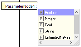
Editing the Name/Type
Name/Type can be edited by the following procedure:
Double-click the name/Type of the diagram element on the Diagram Editor and edit the name.
Edit from the [Base] tab in the Property View.
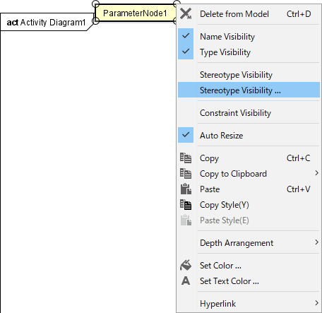
Name/Type Visibility
Select [Name Visibility] or [Type Visibility] to switch the visibility.

Stereotype Visibility …
Sets the stereotype display of figure elements individually.
SendSignalAction and AcceptEventAction
Creating SendSignalAction and AcceptEventAction
SendSignalAction and AcceptEventAction can be created by the following procedure:
Select [SendSignalAction]
in the Tool Bar and click on the diagram.
Select [AcceptEventAction]
in the Tool Bar and click on the diagram.

Editing the SendSignalAction and AcceptEventAction
Editing the name of SendSignalAction/AcceptEventAction
The names of SendSignalAction/AcceptEventAction can be edited by the following procedure: To insert a line break in the name, press either SHIFT + ENTER, ALT + ENTER, or CTRL + ENTER.
Double-click the name of the diagram element on the Diagram Editor and edit the name.
Edit from [Entry] in the [Entry] tab of the Property View.

Reverse Signal
Reverse the selected signal left and right by the following procedure:
Select [Reverse Signal] from the context menu.

Adding a Stereotype
Stereotype can be added by the following procedure:
Select [Add Stereotype] from the context menu.
Add a Stereotype from the [Stereotype] tab of the Property View.
Stereotype Visibility …
Sets the stereotype display of figure elements individually.

AcceptTimeEventAction
Creating an AcceptTimeEventAction
AcceptTimeEventAction can be created by the following procedure:
Select [AcceptTimeEventAction]
in the Tool Bar and click on the diagram.

Editing the AcceptTimeEventAction
Editing the AcceptTimeEventAction Name
AcceptTimeEventAction name can be edited by the following procedure: To insert a line break in the name, press either SHIFT + ENTER, ALT + ENTER, or CTRL + ENTER.
Double-click the name of the diagram element on the Diagram Editor and edit the name.
Edit from [Entry] in the [Entry] tab of the Property View.

Adding a Stereotype
Stereotype can be added by the following procedure:
Select [Add Stereotype] from the context menu.
Add a Stereotype from the [Stereotype] tab of the Property View.
Dependency
Creating a Dependency
Dependency can be created by the following procedure:
Select [Dependency]
in the Tool Bar.

Editing the Dependency
Editing the Name
Name can be edited by the following procedure:
Double-click the name of the diagram element on the Diagram Editor and edit the name.
Edit from the [Base] tab in the Property View.
Editing the Definition
Definition can be edited by the following procedure:
Edit from the [Base] tab in the Property View.
Adding a Stereotype
Stereotype can be added by the following procedure:
Select [Add Stereotype] from the context menu.
Add a Stereotype from the [Stereotype] tab of the Property View.