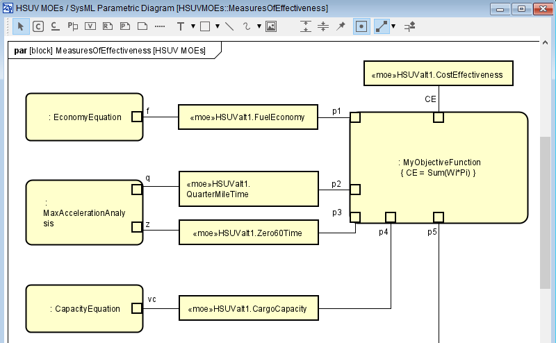
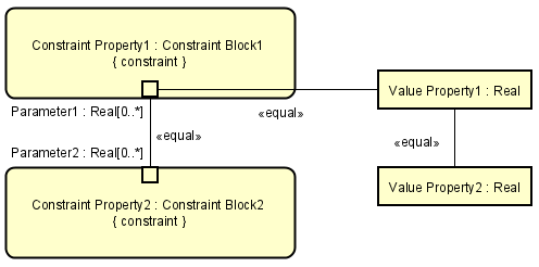
Parametric Diagram
Parametric Diagrams are similar to the Internal Block Diagrams, but are used to represent information about system constraints. These constraints generally take the form of mathematical models and determine the set of valid values in the system. Only binding connectors are available in the Parametric Diagram, and one of the endpoints is connected to the Constraint Parameter.
Creating a Parametric Diagram
Parametric Diagram can be added by the following procedure:
In the Block Definition Diagram, right-click the Block or Constraint Block to create a Parametric Diagram, and click [Parametric Diagram].
A Parametric Diagram is created under the specified Block or Constraint Block.
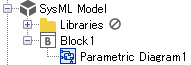
Diagram Element of Parametric Diagram

Description of each icon¶ Type
Icon
Description
Select
The basic operations of the Diagram Editor can be executed in this mode.
Constraint Property
Add a Constraint Property.
Binding Connector
Add a Binding Connector.
Constraint Parameter
Add a Constraint Parameter.
Value Property
Add a Value Property.
Rationale
Add a Rationale.
Problem
Add a Problem.
Refer to Common Diagram Elements for information on other items.

Constraint Property Visibility
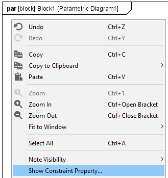
Set whether to show or hide the Constraint Property. Right-click on the diagram to open the context menu and select [Show Constraint Property…]. Then check the Constraint Property to show in the [Show Property] dialog and click the [OK] button.
|
|

Constraint Property
Creating a Constraint Property
Constraint Property can be created by the following procedure:
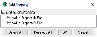
Select [Constraint Property]
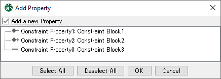
in the Tool Bar and click on the diagram. Then select a property to add from the [Add Property] dialog and click the [OK] button.
A new Constraint Property and Constraint Block are created by checking the [add a new Property] check box.
To add a Constraint Property connected with a parent block by association line, select the property to add and click the [OK] button.
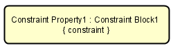
Constraint Property
A new Constraint Property can be created by double-clicking on the Parametric Diagram.
Alternatively, drag and drop a Constraint Block from the structure tree to the Parametric Diagram.
Editing the
Editing the Name
Name can be edited by the following procedure:
Double-click the name of the diagram element on the Diagram Editor and edit the name.
Edit from the [AssociationEnd A]/[AssociationEnd B] tab in the Property View.
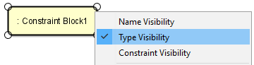
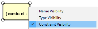
Name/Type/Constraint Visibility
Set whether to show or hide Name, Type, or Constraint by the following procedure:
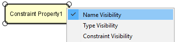
Select [Name Visibility], [Type Visibility], or [Constraints Visibility] from the context menu.
Only Name is selected
Only Type is selected
Only Constraint is selected
Adding a Parametric Diagram
Parametric Diagram can be added by the following procedure:
Select [Add Parametric Diagram] from the context menu.
Binding Connector
Creating a Binding Connector
Binding Connector can be created by the following procedure:
Select [Binding Connector]
on the Tool Bar, click on the diagram, and draw a line between the Constraint Parameters or Value Properties.
Constraint Parameter
Creating a Constraint Parameter
Constraint Parameter can be created by the following procedure:
Select [Constraint Parameter]
on the Tool Bar and click the Constraint Property.
Editing a Constraint Parameter
Editing the Name
Name can be edited by the following procedure:
Double-click the name of the diagram element on the Diagram Editor and edit the name.
Edit from the [Base] tab in the Property View.
Name/Type/Multiplicity Visibility
Set whether to show or hide Name, Type, or Multiplicity by the following procedure:
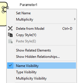
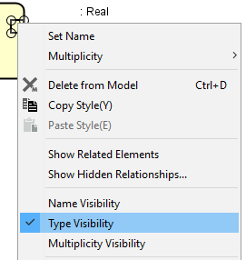
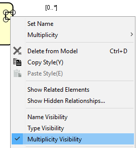
Select [Name Visibility], [Type Visibility], or [Multiplicity Visibility] from the context menu.
Only Name is selected
Only Type is selected
Only Multiplicity is selected
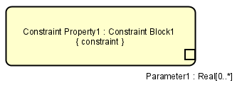
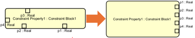
Align Constraint Parameter
You can align the Constraint Parameters within a Constraint Property by following these steps:
Right-click on the Constraint Property containing the Constraint Parameters and select [Align Constraint Parameter] from the context menu.
Select one of the alignment options provided.
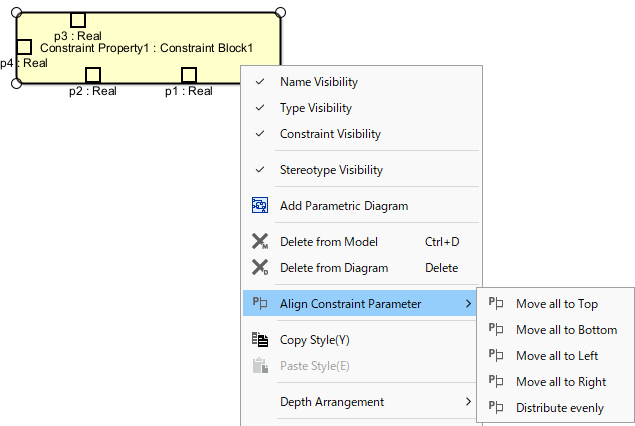
The available alignment options are:
Move all to Top
Move all to Bottom
Move all to Left
Move all to Right
Distribute evenly
Below is an example of the Move all to Right alignment:
Value Property
Creating a Value Property
Value Property can be created by the following procedure:Create a Value Property on the Parametric Diagram created from a Block.
Select [Value Property]
on the Tool Bar and click on the diagram. Then select a property to add from the [Add Property] dialog and click the [OK] button.
A new Value Property and Value Type are created by checking the [Add a new Property] check box.
To add an existing property of the parent block, select the property to add and click the [OK] button.
Value Property
To create a Value Property, select an existing property of the parent block in the structure tree and drag and drop it to the Parametric Diagram.
Editing the Value Property
Editing the Name
Name can be edited by the following procedure:
Double-click the name of the diagram element on the diagram editor and edit the name.
Edit from the [Base] tab in the Property View.
Name/Type Visibility
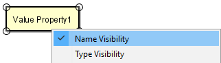
Set whether to show or hide Name and Type by the following procedure:
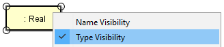
Select [Name Visibility] or [Type Visibility] from the context menu.
Only Name is selected
Only Type is selected