Block Definition Diagram
Block Definition Diagram represents the system hierarchy and the classification of the system and its components.

Creating a Block Definition Diagram
Block Definition Diagram can be added by the following procedure:
Click [Block Definition Diagram] from [Diagram] on the Main Menu.
Use the context menu from [Structure] in the [Project View].
Diagram Elements of Block Definition Diagram

Type |
Icon |
Description |
|---|---|---|
Select |
|
The basic operations of the Diagram Editor can be executed in this mode. |
Package |
|
Add a Package. |
Nest |
|
Add a Nest. |
Block |
|
Add a Block. |
Interface Block |
|
Add an Interface Block. |
Constraint Block |
|
Add a Constraint Block. |
Value Type |
|
Add a Value Type. |
Enumeration |
|
Add an Enumeration. |
Unit |
|
Add an Unit. Select from the pull-down of the Value Type icon. |
QuantityKind |
|
Add a Quantitykind. Select from the pull-down of the Value Type icon. |
Port |
|
Add a Port. |
Full Port |
|
Add a Full Port. Select from the pull-down of the Port icon. |
Proxy Port |
|
Add a Proxy Port. Select from the pull-down of the Port icon. |
Actor |
|
Add an Actor. |
Interface |
|
Add an Interface. |
Interface (Normal) |
|
Add an Interface (Normal). Select from the pull-down of the Interface icon. |
Provided Interface |
|
Add a Provided Interface. |
Required Interface |
|
Add a Required Interface. |
Association (Navigable) |
|
Add an Association (navigable). |
Association (Directed) |
|
Add an Association (Directed). Select from the pull-down of the Association (Navigable). |
Association (Non-navigable) |
|
Add an Association (Non-navigable). Select from the pull-down of the Association (Navigable). |
Aggregation (Navigable) |
|
Add an Aggregation (Navigable). Select from the pull-down of the Association (Navigable). |
Aggregation (Directed) |
|
Add an Aggregation (Directed). Select from the pull-down of the Association (Navigable). |
Composition (Navigable) |
|
Add an Composition (Navigable). Select from the pull-down of the Association (Navigable). |
Composition (Directed) |
|
Add an Composition (Directed). Select from the pull-down of the Association (Navigable). |
Generalization |
|
Add a Generalization. |
Dependency |
|
Add a Dependency. |
Allocate Dependency |
|
Add an Allocate Dependency. Select from the pull-down of the Dependency icon. |
Realization |
|
Add a Realization. |
Usage Dependency |
|
Add a Usage Dependency. |
InstanceSpecification |
|
Add an Instance Specification. |
Link |
|
Add a Link. |
Refer to Common Diagram Elements for information on other items. |


Package
Creating a Package
Package can be created by the following procedure:
Select [Package]
in the Tool Bar and click on the diagram.
Use the structure tree context menu in the [Project View].

Editing the Package
Editing the Name
Name can be edited by the following procedure:
Double-click the name of the diagram element on the Diagram Editor and edit the name.
Edit from the [Base] tab in the Property View.
Adding a Stereotype
Stereotype can be added by the following procedure:
Select [Add Stereotype] from the context menu.
Add a stereotype from the [Stereotype] tab of the Property View.
Special Operation of a Package
Operate the models in package units on the Diagram Editor. Drag and drop the diagram element to the Package.


Nest
Creating a Nest
Nest can be created by the following procedure:
Select [Nest]
in the Tool Bar.
Select [Nest] using the Draw Suggest Feature.

Block/Interface Block
Creating a Block and Interface Block
Creating a Block
Block can be created by the following procedure:
Double-click on the Block Definition Diagram.
Select [Block]
in the Tool Bar and click on the diagram.

Creating an Interface Block
Interface Block can be created by the following procedure:
Select [Interface]
from the [Block] pull-down in the Tool Bar and click on the diagram.

Editing the Block/Interface Block
Editing the Name
Name can be edited by the following procedure:
Double-click the name of the diagram element on the Diagram Editor and edit the name.
Edit from the [Base] tab in the Property View.
Adding a Stereotype
Stereotype can be added by the following procedure:
Select [Stereotype] from [Add Element] of the context menu.
Add a stereotype from the [Stereotype] tab of the Property View.
Add an Internal Block Diagram
Internal Block diagram can be added by the following procedure:
Select [Add Internal Block Diagram] from the context menu of the Block or Interface Block to which no related internal block diagram is set.

Open Internal Block Diagram
Internal Block Diagram can open by the following procedure:
Select [Open Internal Block Diagram] from the context menu of the Block or Interface Block to which related internal block diagrams are set.

Adding a Parametric Diagram
Parametric Diagram can be added by the following procedure:Parametric Diagram cannot be created in an Interface Block.
Select [Add Parametric Diagram] from the context menu of the Block or Constraint Block to which no related Parametric Diagram is set.

Open Parametric Diagram
Parametric Diagram can open by the following procedure:
Select [Open Parametric Diagram] from the context menu of the Block or Constraint Block to which related Parametric Diagrams are set.

Compartment Visibility
Set whether to show or hide the Compartment by the following procedure:
Select from [Compartment Visibility] in the context menu.
Block

Interface Block

Constraint Compartment
Adding a Constraint
Constraint can be added by the following procedure:
Select [Constraint] from [Add Element] of the context menu.
Click
in the Constraint Compartment.
Add a constraint from the [Constraint] tab of the Property View.

Deleting a Constraint
Constraint can be deleted by the following procedure:
Delete a Constraint from the [Constraint] tab of the Property View.
Select the Constraint to delete and press the [Delete] key.
Operation Compartment
Adding an Operation
Operation can be added by the following procedure:
Select [Operation] from [Add Element] of the context menu.
Click
Add from the [Operation] tab of the Property View.

Deleting an Operation
Operation can be deleted by the following procedure:
Select the Operation to delete from [Delete Element] - [Operation] of the context menu.
Delete the Operation from the [Operation] tab of the Property View.
Select the Operation to delete and press the [Delete] key.

Operation Return Type Visibility
Set whether to show or hide the Operation Return Type by the following procedure:
Select [Operation Return Type] from [Extended Visibility] in the context menu.
Operation Parameter Visibility
Set whether to show or hide the Operation Parameter by the following procedure:
Select [Operation Parameter] from [Extended Visibility] in the context menu.
Operation Parameter Type Visibility
Set whether to show or hide the Operation Parameter Type by the following procedure:
Select [Operation Parameter Type] from [Extended Visibility] in the context menu.
Operation Parameter Direction Kind Visibility
Set whether to show or hide the Operation Parameter direction kind by the following procedure:
Select [Operation Parameter Direction Kind] from [Extended Visibility] in the context menu.
Operation Stereotype Visibility
Set whether to show or hide the Operation Stereotype by the following procedure:
Select [Operation Stereotype] from [Extended Visibility] in the context menu.
Operation Constraint Visibility
Set whether to show or hide the Operation Constraint the following procedure:
Select [Operation Constraint] from [Extended Visibility] in the context menu.
Flow Property Compartment
Add Flow Property
Flow Property can be added by the following procedure:
Select [Flow Property] from [Add Element] of the context menu.
Click
Add from the [Flow Property] tab of the Property View.

Deleting a Flow Property
Flow Property can be deleted by the following procedure:
Select the Flow Property to delete from [Delete Element] - [Flow Property] of the context menu.
Delete from the [Flow Property] tab of the Property View.
Select the Flow Property to delete and press the [Delete] key.

Type Visibility of Flow Property
Set whether to show or hide the Type Visibility of Flow Property by the following procedure:
Select [Property Type] from [Extended Visibility] in the context menu.
Unit Visibility of Flow Property
Set whether to show or hide the Unit Visibility of Flow Property by the following procedure:
Select [Property Unit] from [Extended Visibility] in the context menu.
Stereotype Visibility of Flow Property
Set whether to show or hide the Stereotype Visibility of Flow Property by the following procedure:
Select [Property Stereotype] from [Extended Visibility] in the context menu.
Constraint Visibility of Flow Property
Set whether to show or hide the Constraint Visibility of Flow Property by the following procedure:
Select [Property Constraint] from [Extended Visibility] in the context menu.
Part Compartment
Part Compartment does not exist in an Interface Block.
Adding a Part
Part can be added by the following procedure:
Select [Part] from [Add Element] of the context menu.
Click

Create [Composition]

for a different Block.

Deleting a Part
Part can be deleted by the following procedure:
Select the part to delete from [Delete Element] - [Part] of the context menu.
Delete from the [Association] tab of the Property View.

Reference Compartment
Adding a Reference
Reference can be added by the following procedure:
Select [Reference] from [Add Element] of the context menu.
Click

Create [Association]

or [Aggregation]

for a different Block.

Deleting the Reference
Reference can be deleted by the following procedure:
Select the reference to delete from [Delete Element] - [Reference] of the context menu.
Delete from the [Association] tab of the Property View.

Value Compartment
Value Compartment does not exist in an Interface Block.
Adding a Value
Value can be added by the following procedure:
Select [Value] from [Add Element] of the context menu.
Click
Add from the [Value] tab of the Property View.

Deleting the Value
Value can be deleted by the following procedure:
Select the Value to delete from [Delete Element] - [Value] of the context menu.
Delete from the [Value] tab of the Property View.
Select the Value to delete and press the [Delete] key.

Value Type Visibility
Set whether to show or hide the Value Type by the following procedure:
Select [Property Type] from [Extended Visibility] in the context menu.
Value Initial Value Visibility
Set whether to show or hide the Value Initial Value by the following procedure:
Select [Property Initial value] from [Extended Visibility] in the context menu.
Value Unit Visibility
Set whether to show or hide the Value Unit by the following procedure:
Select [Property Unit] from [Extended Visibility] in the context menu.
Value Stereotype Visibility
Set whether to show or hide the Value Stereotype by the following procedure:
Select [Property Stereotype] from [Extended Visibility] in the context menu.
Value Constraint Visibility
Set whether to show or hide the Value Constraint by the following procedure:
Select [Property Constraint] from [Extended Visibility] in the context menu.
Port/Proxy Port/Full Port Compartment
Refer to Port/Proxy Port/Full Port for details.
Constraint Block
Creating a Constraint Block
Constraint Block can be created by the following procedure:
Select [Constraint Block]
in the Tool Bar and click on the diagram.

Editing the Constraint Block
Editing the Name
Name can be edited by the following procedure:
Double-click the name of the diagram element on the Diagram Editor and edit the name.
Edit from the [Base] tab in the Property View.
Adding a Stereotype
Stereotype can be added by the following procedure:
Select [Stereotype] from [Add Element] of the context menu.
Add a Stereotype from the [Stereotype] tab of the Property View.
Adding a Parametric Diagram
Refer to Add Parametric Diagram for details.
Compartment Visibility
Set whether to show or hide the Compartment by the following procedure:
Select from [Compartment Visibility] in the context menu.

Constraint Compartment
Refer to Constraint Compartment for details.
Parameter Compartment
Adding a Parameter
Parameter can be added by the following procedure:
Select [Parameter] from [Add Element] of the context menu.
Click
Add from the [Parameter] tab of the Property View.

Deleting the Parameter
Parameter can be deleted by the following procedure:
Select the Parameter to delete from [Delete Element] - [Parameter] of the context menu.
Delete from the [Parameter] tab of the Property View.
Select the Parameter to delete and press the [Delete] key.

Parameter Type Visibility
Set whether to show or hide the Parameter Type by the following procedure:
Select [Property Type] from [Extended Visibility] in the context menu.
Parameter Initial Value Visibility
Set whether to show or hide the parameter initial value visibility by the following procedure:
Select [Property Initial value] from [Extended Visibility] in the context menu.
Parameter Unit Visibility
Set whether to show or hide the Parameter Unit visibility by the following procedure:
Select [Property Unit] from [Extended Visibility] in the context menu.
Parameter Stereotype Visibility
Set whether to show or hide the Parameter Stereotype visibility by the following procedure:
Select [Property Stereotype] from [Extended Visibility] in the context menu.
Parameter Constraint Visibility
Set whether to show or hide the Parameter Constraint by the following procedure:
Select [Property Constraint] from [Extended Visibility] in the context menu.
Value Type
Creating a Value Type
Value Type can be created by the following procedure:
Select [Value Type]
in the Tool Bar and click on the diagram.

Editing a Value Type
Editing the Name
Name can be edited by the following procedure:
Double-click the name of the diagram element on the Diagram Editor and edit the name.
Edit from the [Base] tab in the Property View.
Adding a Stereotype
Stereotype can be added by the following procedure:
Add a stereotype from the [Stereotype] tab of the Property View.
Compartment Visibility
Set whether to show or hide the Compartment by the following procedure:
Select from [Compartment Visibility] in the context menu.

Operation Compartment
Refer to Operation Compartment for details.
Property Compartment
Adding a Property
Property can be added by the following procedure:
Select [Property] from [Add Element] of the context menu.
Click
Add from the [Property] tab of the Property View.

Deleting a Property
Property can be deleted by the following procedure:
Select the property to delete from [Delete Element] - [Property] of the context menu.
Delete from the [Property] tab of the Property View.
Select the property to delete and press the [Delete] key.

Property Type Visibility
Set whether to show or hide the Property Type visibility by the following procedure:
Select [Property Type] from [Extended Visibility] in the context menu.
Property Initial Value Visibility
Set whether to show or hide the Property Initial Value by the following procedure:
Select [Property Initial Value] from [Extended Visibility] in the context menu.
Property Unit Visibility
Set whether to show or hide the Property Unit by the following procedure:
Select [Property Unit] from [Extended Visibility] in the context menu.
Property Stereotype Visibility
Set whether to show or hide the Property Stereotype visibility by the following procedure:
Select [Property Stereotype] from [Extended Visibility] in the context menu.
Property Constraint Visibility
Set whether to show or hide the Property Constraint Visibility by the following procedure:
Select [Property Constraint] from [Extended Visibility] in the context menu.
Value Type Compartment
Adding a Value Type
Value type can be added by the following procedure:
Select [Unit] or [QuantityKind] from the [Add Element] - [ValueType] in the context menu.
Add from the [Base] tab of the Property View.

Deleting a Value Type
Value type can be deleted by the following procedure:
Select [Unit] or [QuantityKind] from [Delete Element] - [ValueType] in the context menu.
Delete from the [Base] tab of the Property View.

Enumeration
Creating an Enumeration
Enumeration can be created by the following procedure:
Select [Enumeration]
in the Tool Bar and click on the diagram.

Editing an Enumeration
Editing the Name
Name can be edited by the following procedure:
Double-click the name of the diagram element on the Diagram Editor and edit the name.
Edit from the [Base] tab in the Property View.
Adding a Stereotype
Stereotype can be added by the following procedure:
Add a stereotype from the [Stereotype] tab of the Property View.
Compartment Visibility
Set whether to show or hide the Compartment by the following procedure:
Select from [Compartment Visibility] in the context menu.

Operation Compartment
Refer to Operation Compartment for details.
Property Compartment
Refer to Property Compartment for details.
Enumeration Literal Compartment
Adding an Enumeration Literal
Enumeration Literal can be added by the following procedure:
Select [Enumeration Literal] from the [Add Element] in the context menu.
Add from the [Enumeration Literal] tab of the Property View.

Deleting an Enumeration Literal
Value type can be deleted by the following procedure:
Select [Enumeration Literal] from the [Delete Element] in the context menu.
Delete from the [Enumeration Literal] tab of the Property View.

Value Type Compartment
Refer to Value Type Compartment for details.
Unit/QuantityKind
Creating a Unit/QuantityKind
Unit can be created by the following procedure:
Select [Unit]
/[QuantityKind]
in the Tool Bar and click on the diagram.
Create in Add Value Type of Value Type

Unit/QuantityKind
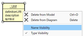
Name/Type Visibility
Select [Name Visibility] or [Type Visibility] to switch the visibility.
Only the Name is displayed

Only the Type is displayed
Editing the Slot
Symbol, DefinitionURI, and Description can be edited by the following procedure:
Double-click the Symbol, DefinitionURI, or Description in the Diagram Editor and edit it.
Edit from the [Base] tab in the Property View.

Slot Visibility
Set whether to show or hide the Symbol, DefinitionURI, or Description by the following procedure:
Select or [Slot Visibility] from the context menu.
The slot is hidden

Slot Value Visibility
Set whether to show or hide the value of Symbol, DefinitionURI, or Description by the following procedure:
Select [Slot Value Visibility] from the context menu.

Slot-without-Value Visibility
Set whether to show or hide the Symbol, DefinitionURI, or Description which has no value by the following procedure:
Select [Slot-without-Value Visibility] from the context menu.

Port/Full Port/Proxy Port
Creating Port/Full Port/Proxy Port
Port/Full Port/Proxy Port can be created by the following procedure: Created Port/Full Port/Proxy Port is displayed in each Compartment.
Select [Port]
, [Full Port]
, or [Proxy Port]
in the Tool Bar and click the border of the block/Interface Block.
Port

Full Port

Proxy Port

Editing Port/Full Port/Proxy Port
Name Setting
The names of Port/Full Port/Proxy Port can be created by the following procedure:
Configure the settings of [Name Setting] from the context menu.
Set from the [Base] tab of the Property View.
Double-click the existing name of the Port/Full Port/Proxy Port and rename it.

Multiplicity
The Multiplicity of the Port/Full Port/Proxy Port can be created by the following procedure:
Select [Multiplicity] in the context menu and click [1], [0..1], [0..*], [*], [1..*], or [Unspecified].

Editing the Type
The type of the Port/Full Port/Proxy Port can be edited by the following procedure:
Set from the [Base] tab of the Property View.
To set from the context menu
Select [Edit Flow Property] from [Edit Direction] of the context menu.
When no type is specified, [Block] can be newly created for the Port/Full Port, and [Interface Block] for the Proxy Port.
Port or Full Port
Proxy Port
Edit from the dialog of [Block] for the Port/Full Port, and [Interface Block] for the Proxy Port.
Port or Full Port
Proxy Port


isConjugated ON/OFF
isConjugated ON/OFF can be set by the following procedure:
Select [isConjugated] from [Edit Direction] of the context menu.
Set from the [Base] tab of the Property View.

Port Notation
Port notation depends on the Flow Property direction of the Port type. The direction can be changed from the dialog.
No Flow Property
Flow Property direction is [inout]
Flow Property direction is [out]
Flow Property direction is [in]


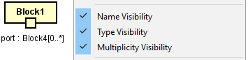
Name/Type/Multiplicity Visibility
Set whether to show or hide Name/Type/Multiplicity by the following procedure:
Select [Name Visibility], [Type Visibility], or [Multiplicity Visibility] from the context menu.
Align Ports
The diagram elements in the created Port/Full Port/Proxy Port can be aligned by the following procedure:
Select [Align Ports] in the context menu of the Block in which the Port is created.
Select either of the alignment.

There are six alignments as follows:
Move all to Top
Move all to Bottom
Move all to Left
Move all to Right
Align by its direction
Distribute evenly
The image below is the example of [Move all to Right].

Actor
Refer to Actor Properties for details.
Interface/Required Interface/Provided Interface
Creating an Interface/Required Interface/Provided Interface
Interface can be created by the following procedure:
Use [Interface]
, [Interface (Normal)]
, [Provided Interface]
, or [Required Interface]
in the Tool Bar.
The Interface is represented on a diagram by Icon Notation (Left) or Normal Notation (Right).


Editing an Interface
Adding an Attribute
Attribute can be added by the following procedure:
Select [Add Attribute] from the context menu.
Click the Attribute icon of Draw Suggest.
Add from the structure tree or Property View of the Attribute.

Deleting an Attribute
Attribute can be deleted by the following procedure:
Select the Attribute to delete from [Delete Attribute] in the context menu.
Select the Attribute on the diagram and press the [Delete] key.
Add from the structure tree or Property View of the Attribute.
Adding an Operation
Operation be added by the following procedure:
Select [Add Operation] from the context menu.
Click the Operation icon of Draw Suggest.
Add from the structure tree or Property View of the Operation.

Deleting the Operation
Operation can be deleted by the following procedure:
Select the Operation to delete from [Delete Operation] in the context menu.
Select the Operation on the diagram and press the [Delete] key.
Add from the structure tree or Property View of the Operation.
Shortcut key of the Attribute or Operation on the Diagram Editor
[Enter] - Creates Attributes or Operations continuously that are in selected status.
[Shit + Enter] - Creates new Attribute or Operation on the selected Attribute or Operation.
Change depth: [Ctrl+UP] - Move up, [Ctrl+DOWN] - Move down
Copy, paste: [Ctrl+C] - Copy, [Ctrl+V] - Paste
Editing the Interface Name
Interface name can be edited by the following procedure:
Double-click the name of the diagram element on the Diagram Editor and edit the name.
Edit from the [Base] tab in the Property View.
Attribute Compartment Visibility, Operations Compartment Visibility
Select Attribute Compartment Visibility or Operations Compartment Visibility for Interface in the context menu.
Extended Visibility
Namespace
Namespace belongs to the Interface name can be displayed by the following procedure:
Select [Show/Hide Namespace] from the context menu and select the hierarchy.
None
Add no Namespace.
Parent
Add a Namespace.
All Parents
Add all Namespaces.

Each Visibility for Attribute and Operation
Visibility can be set for the Interface Attribute or Interface Operation individually from the context menu.
Select [Extended Visibility] - [Each Attribute/Operation …] in the context menu.
A list of Attributes and Operations in the class is displayed in the dialog.
Check ON the check boxes of the Attributes and Operations to show and press [OK].

Association
Refer to UseCase Diagram Association for details.
Generalization
Refer to UseCase Diagram Generalization for details.
Dependency/Allocate Dependency
Creating a Dependency/Allocate Dependency
Dependency/Allocate Dependency can be created by the following procedure:
Select [Dependency]
or [Allocate Dependency]
in the Tool Bar and create.
Select [Dependency] or [Allocate Dependency] using the Draw Suggest Feature and create.
Dependency

Allocate Dependency

Editing the Dependency/Allocate Dependency
Editing the Name
Name can be edited by the following procedure:
Click [Set Name] from the context menu.
Double-click the existing name to edit.
Edit from the [Base] tab in the Property View.
Adding a Constraint
Constraint can be added by the following procedure:
Click [Add Constraint] from the context menu.
Edit from the [Constraint] tab of the Property View.
Adding a Stereotype
Stereotype can be added by the following procedure:
Select [Add Stereotype] from the context menu.
Add a Stereotype from the [Stereotype] tab of the Property View.
Realization/Usage Dependency
Creating a Realization/Usage Dependency
Realization/Usage Dependency can be created by the following procedure:
Select [Realization]
or [Usage Dependency]
and draw a line from the Port/Full Port/Proxy Port to the Interface.
If no type is specified for the Port or Full Port, the new Block creation dialog is displayed.
If no type is specified for the Proxy Port, the new Interface Block creation dialog is displayed.
Realization

Usage Dependency

Editing the Realization/Usage Dependency
Editing the Name
Name can be edited by the following procedure:
Click [Set Name] from the context menu.
Double-click the existing name to edit.
Edit from the [Base] tab in the Property View.
Adding a Constraint
Constraint can be added by the following procedure:
Click [Add Constraint] from the context menu.
Edit from the [Constraint] tab of the Property View.
Adding a Stereotype
Stereotype can be added by the following procedure:
Select [Add Stereotype] from the context menu.
Add a Stereotype from the [Stereotype] tab of the Property View.
Instance Specification
Creating a Instance Specification
Instance Specification can be created by the following procedure:
Select [InstanceSpecification]
in the Tool Bar and click on the diagram.

Editing the Instance Specification
Editing the Name
Name can be edited by the following procedure:
Double-click the name of the diagram element on the Diagram Editor and edit the name.
Edit from the [Base] tab in the Property View.

Editing the Type
The type of the Instance Specification can be edited by the following procedure:
Double-click the type of the diagram element on the Diagram Editor and edit the name.
Edit from the [Base] tab in the Property View.


Each Stereotype Visibility
Display the context menu of the diagram element which Multi Stereotype Visibility Chooser is to be set.
Select [Extended Visibility] - [Stereotype …].
In the [Multi Stereotype Visibility Chooser] dialog, select the Stereotype to show.

Visibility of each Stereotype can also be set for multiple different model elements.
With multiple diagram elements selected, select [Stereotype Visibility …] in the context menu.
In the [Multi Stereotype Visibility Chooser] dialog, select the Stereotype to show.

Note
- The [Multi Stereotype Visibility Chooser] dialog does not support the following items:
Operation or Property Stereotype
Association line Stereotype