
UseCase Diagram

UseCase Diagrams in Astah represent system functions and interactions between external actors and the system.


Creating an Actor

- Select [Actor] from the tool palette.
- Choose from Normal Actor or Business Actor (not supported in Astah SysML or Astah System Safety).

- Click on the diagram to place it.
Creating a UseCase

- Double-click anywhere on the diagram or select UseCase from the tool palette.
- Choose from Normal UseCase or Business UseCase (not supported in Astah SysML or Astah System Safety).

Adding Extension Points

- Right-click a UseCase and select [Add Extension Point].

- The Extension Point appears below the UseCase name.
Show UseCase name outside

Right-click a UseCase and choose [Name in Oval] to toggle the name display position.
Extend / Include Relationships

You can create Extend and Include relationships using the suggest feature:
- Hover over a UseCase until a mini icon appears.
- Choose [E] for Extend or [I] for Include and drag to the target UseCase.


Important:
Dependencies with the stereotypes «extend» or «include» are not recognized as true UML relationships by Astah.
UseCase Description
You can create a UseCase Description for each UseCase.

Note:
UseCase Descriptions are not supported in Astah System Safety or Astah SysML.
Open / Create a UseCase Description
- Right-click a UseCase → [Open UseCase Description]

Switch Templates
Astah provides three pre-installed templates:
- Astah Original (Default)
- Complete Format by Alistair Cockburn
- RUP Style
Go to [Tools] → [Template Settings] → [UseCase Description] to switch between templates.


Create a Custom Template
- Go to [Tools] → [Template Settings] → [UseCase Description]
- Click [New], customize the template, and click [OK]

- The customized template is saved as UCDescriptionProp.properties in your user directory
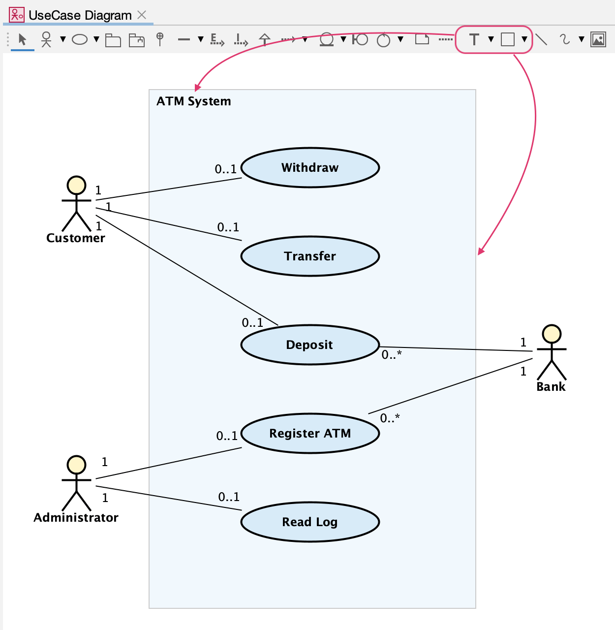
Drawing a System Boundary
A System Boundary visually defines the scope of the system being modeled.
To draw it:
- Select the Rectangle tool from the tool palette.
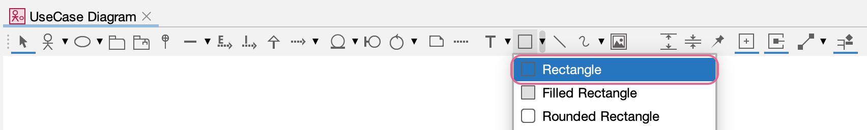
- Draw a rectangle that encloses the UseCases belonging to the system.
- Optionally, label the boundary with the system name using the text tool from the tool palette.
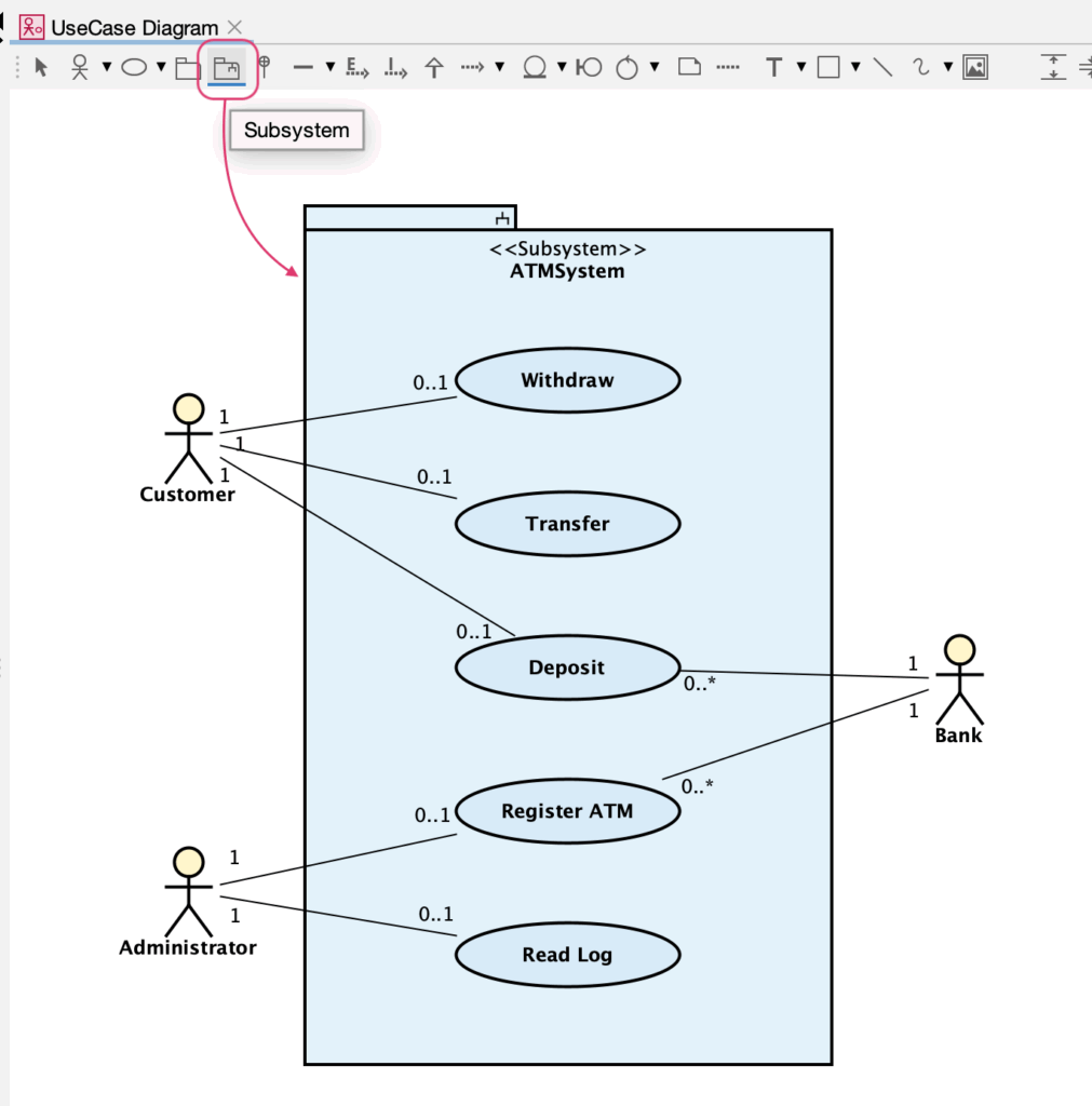
or you can use the Subsystem model from the tool palette and use it instead of the rectangle.
Sample Image Reference: Figure 18.2 Class diagram of a Package owning a set of UseCases, Actors, and a Subsystem from Unified Modeling Language 2.5.1