
ER Diagram
Astah Professional allows you to create and manage Entity-Relationship Diagrams (ER Diagrams) using IDEF1X or IE notation. You can also auto-generate ER diagrams by reverse-engineering tables from your databse.
Because all models are stored centrally, you can easily convert ER models into other formats, such as UML Class Diargams.
Creating ER Diagram
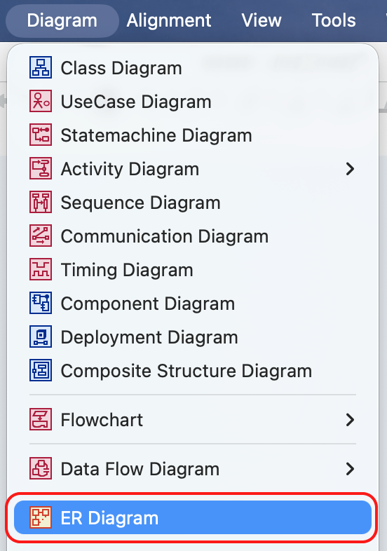
- Go to [Diagram] – [ER Diagram] from Main Menu.
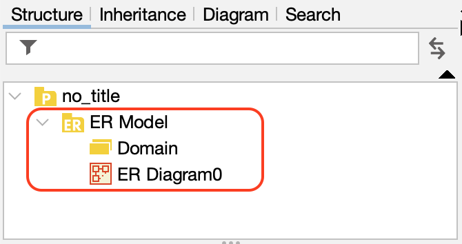
- An ER Diagram will be created under the [ER Model] package in the Structure Tree.
Auto-generate ER Diagram
You can automatically generate ER Diagrams by importing database tables using the DB Reverse Plug-in.
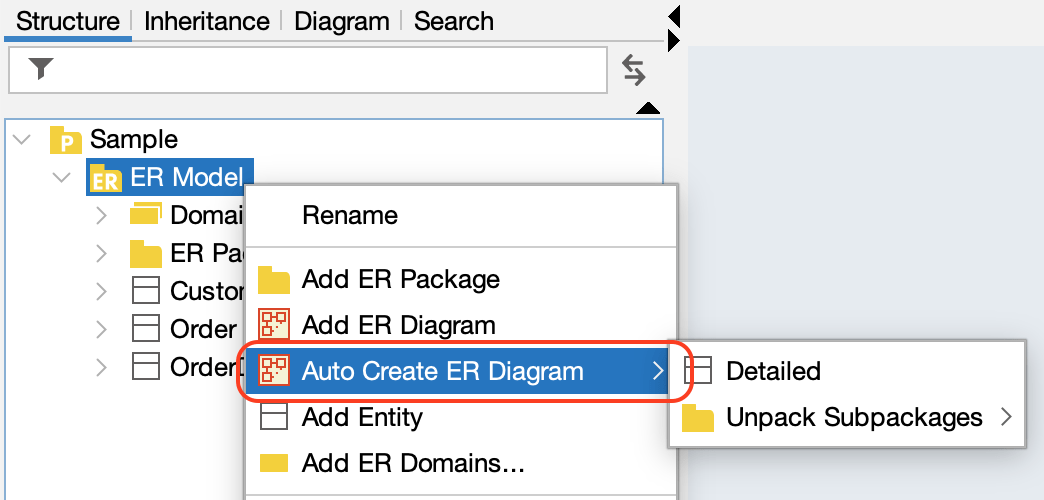
- Right-click the target ER Model in the Structure Tree
- Select [Auto Create ER Diagram]
- Choose your preferred generation method.
- The diagram will be created and opened automatically.
Logical and Physical name
Astah allows you to manage both Logical and Physical names for entities. You can switch the display between these two types using one of the following methods: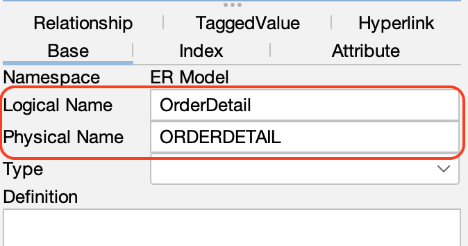
There are three ways to switch the display of names logical or physical.
1. Right-click on the diagram background and select [Diagram Model Type].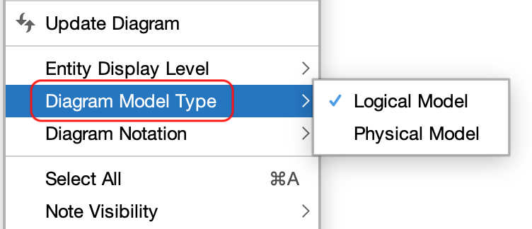
2. Click [Diagram Model Type] in the Structure Tree.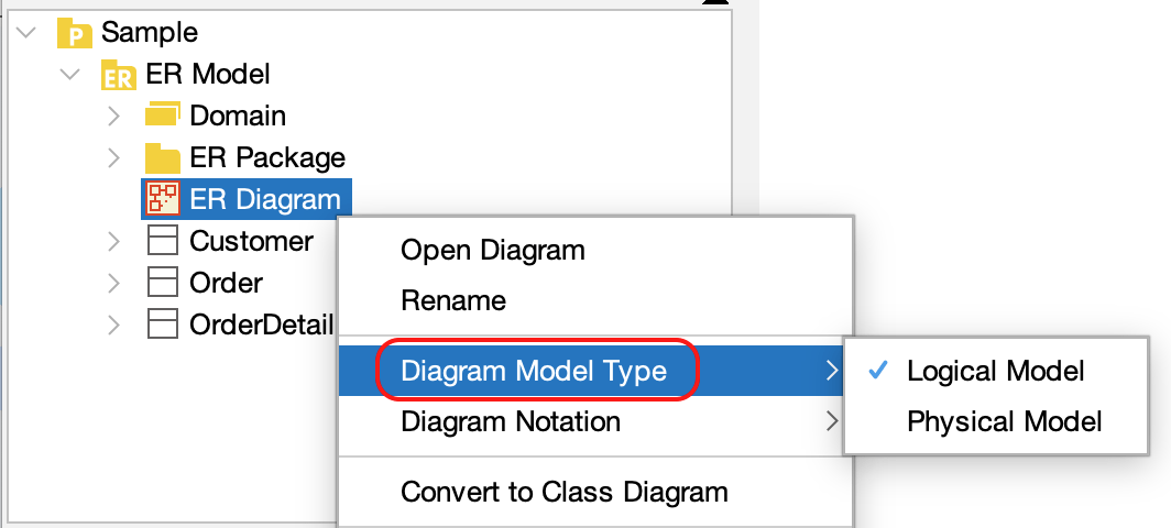
3. Switch from the ER Diagrams’ Property View (bottom-left pane).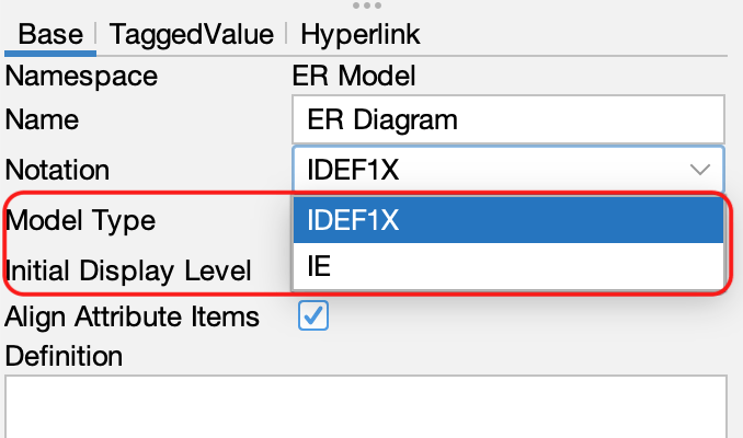
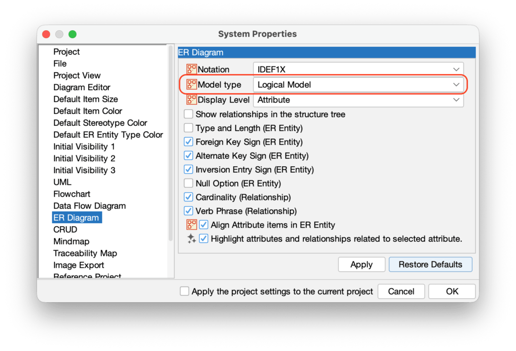
TIP: You can set the default name type in [Tools] → [System Properties] → [ER Diagram].
Switching Notations (IDEF1X and IE)
You can switch between IDEF1X and IE notation for your ER diagrams.
1. Right-click the ER diagram in the Structure Tree and select [Diagram Notation].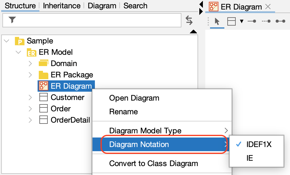
ER Entity
Creating an ER Entities
Astah provides several ways to create ER Entities – please refer to the the Diagram Editor page.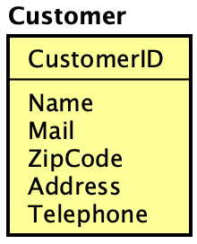
Adding Primary Keys and Attributes
There are multiple ways to add Primary Keys and Attributes to ER Entities:
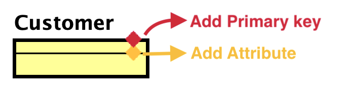
Using the Suggest Feature:
Hover over and ER Entity to reveal mini icons.
- Click the red diamond to add a Primary key
- Click the orange diamond to add an Attribute
Once you add an item, press [Enter] to create another.
Alternatively, you are able to add Primary keys and Attributes by pasting text.
Display Level and Extended Visibility
There are three display levels for ER Entities. Entity, Primary key and Attribute.
To change the level, right-click an ER Entity and select [Display Level] from the menu.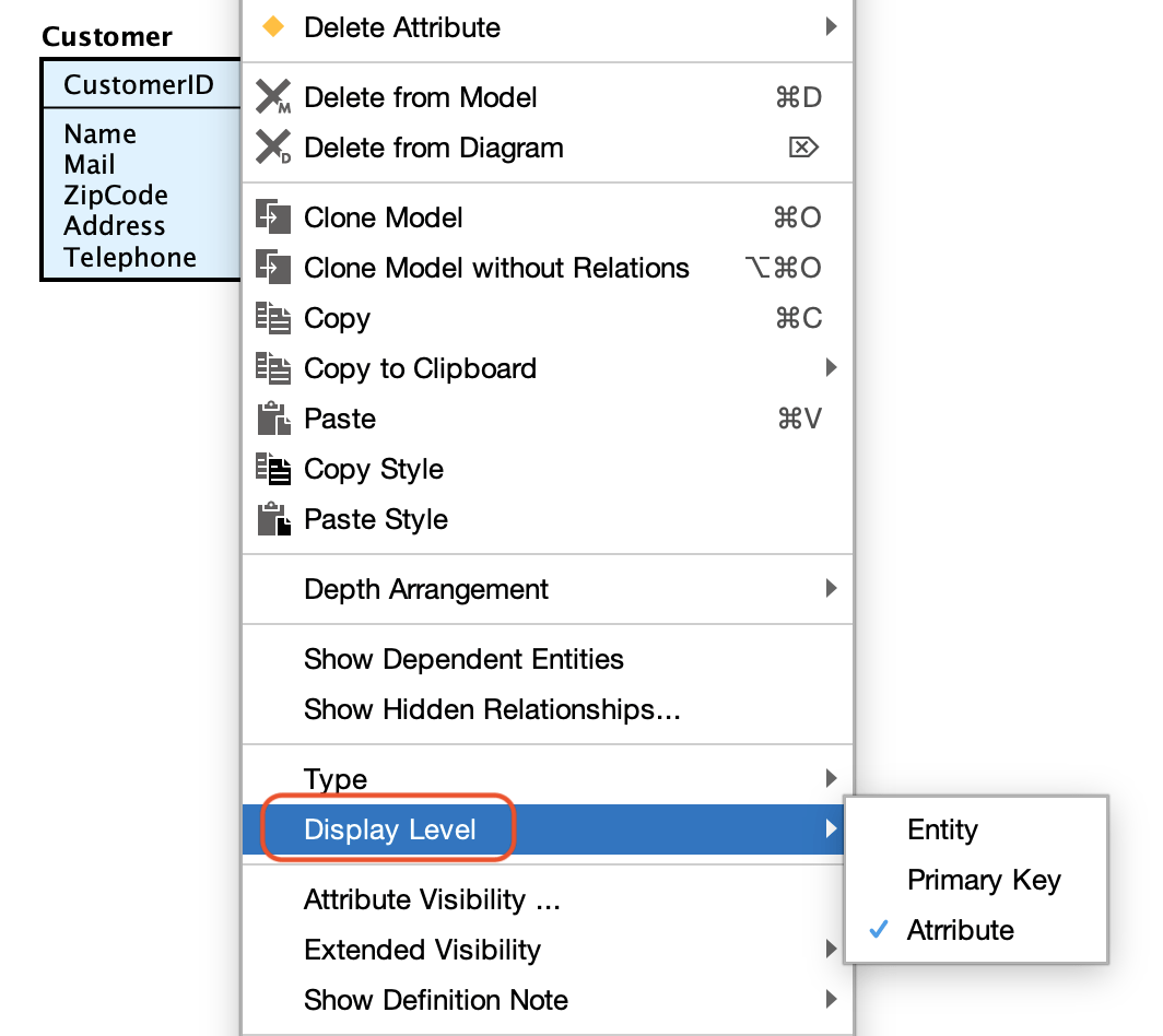
To show additional details such as data types and lengths, select [Extended Visibility] from the context menu and check the items you with to display.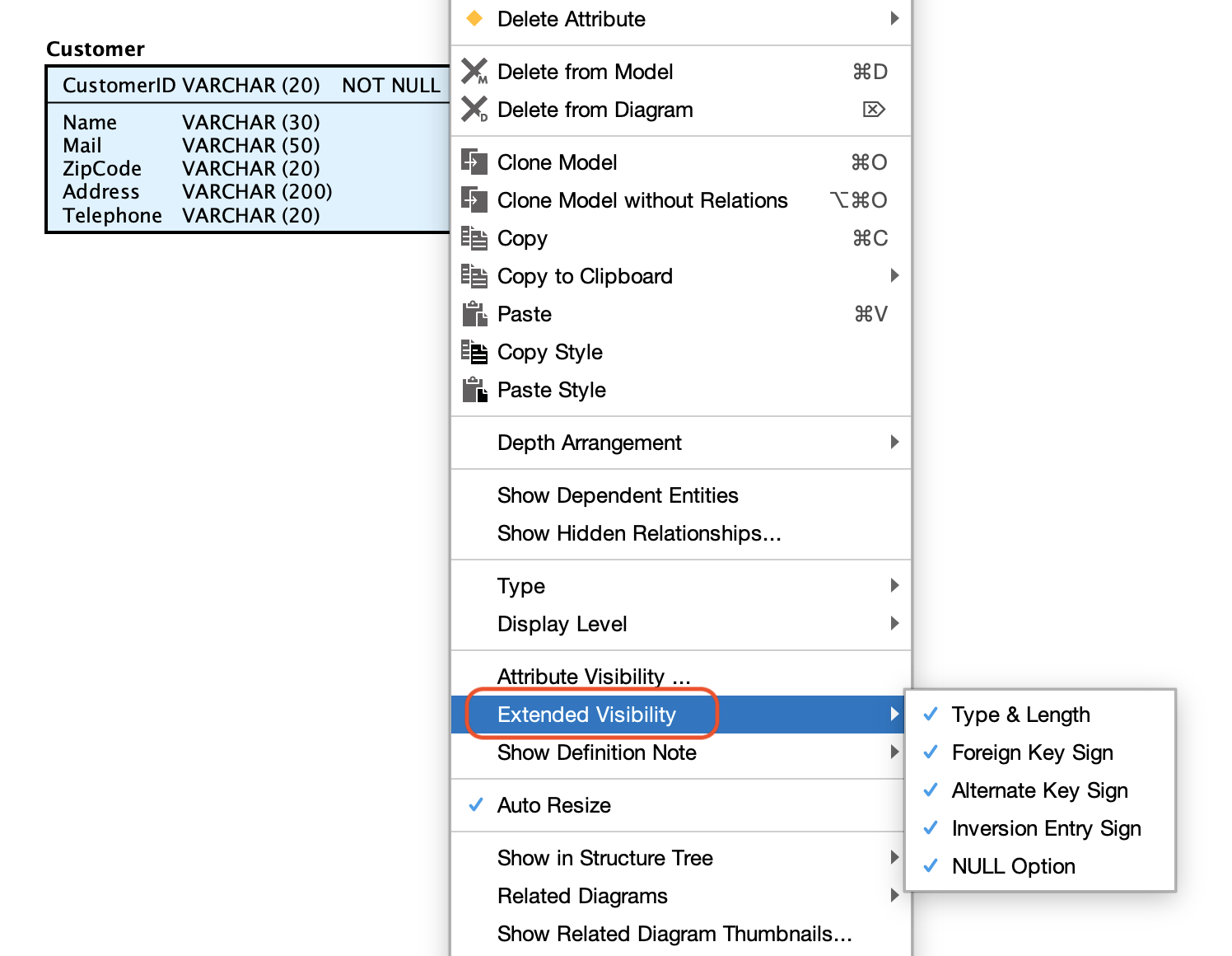
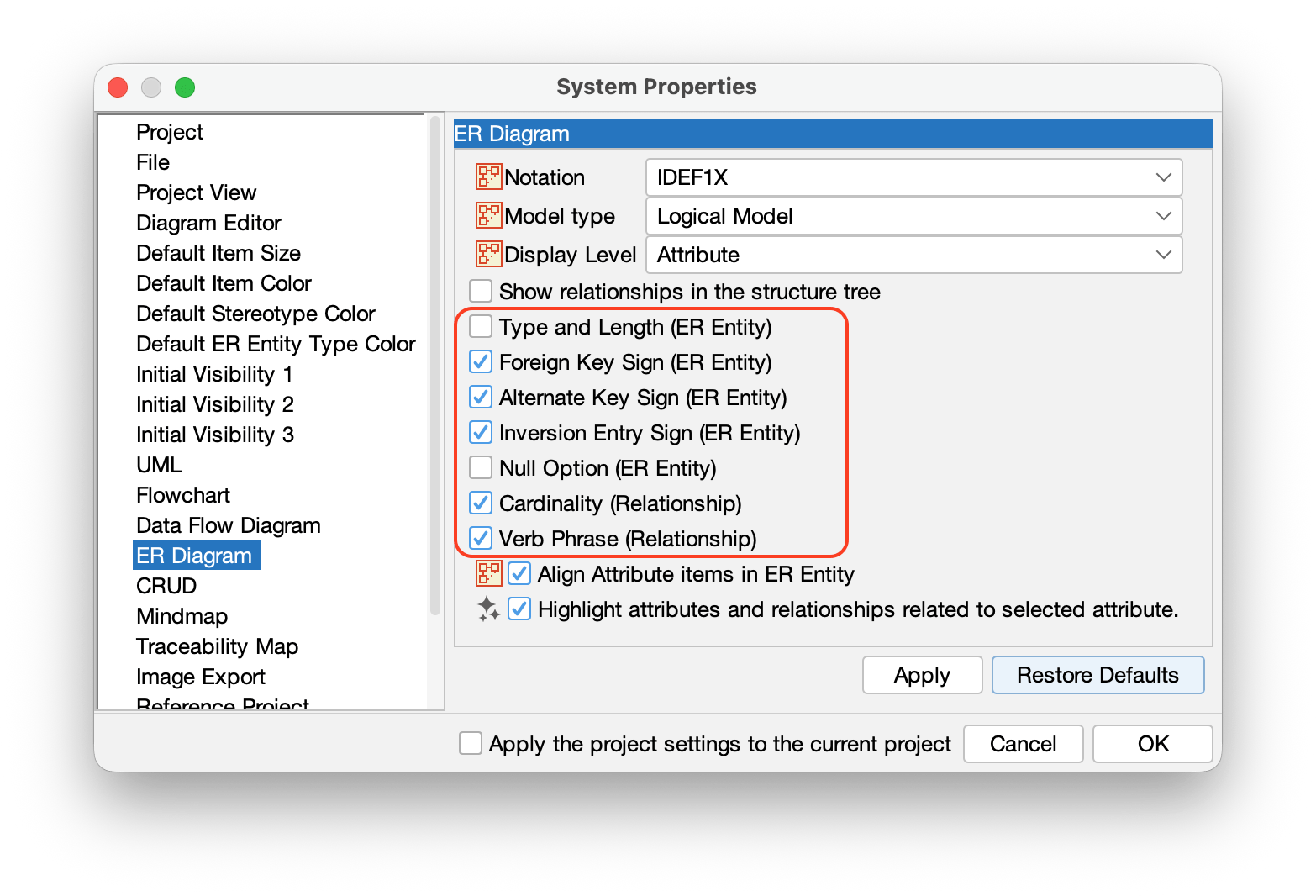
TIPS: You can set the default display settings in [Tools] → [System Properties] → [ER Diagram].
Managing Domains
Creating a Single Domain
Right-click [Domain] in the Structure Tree and select [Add ER Domain].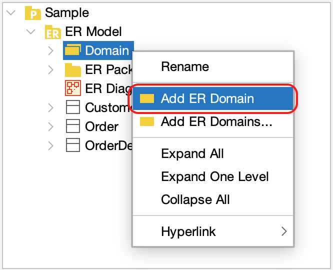
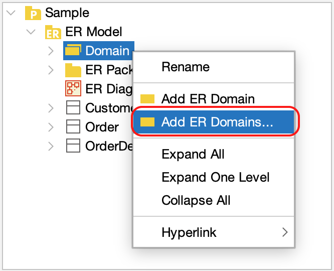
Creating Multiple Domains
You can add multiple domains at once:
- Right-click [Domain] in the Structure Tree and select [Add ER Domains], or go to [Tools] > [ER Diagram] > [Add ER Domains].
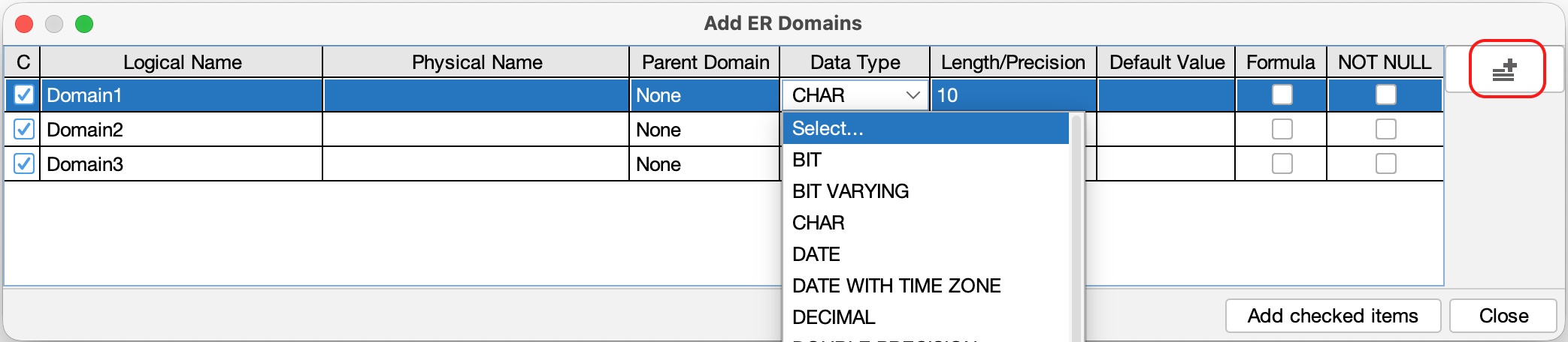
- A domain configuration window opens, click [Add] icon on the right and enter the details for each domain in the list provided.
Applying a Domain to an Entity
To apply a domain, drag it from the Structure Tree and drop it directly onto ER Entity in the diagram.
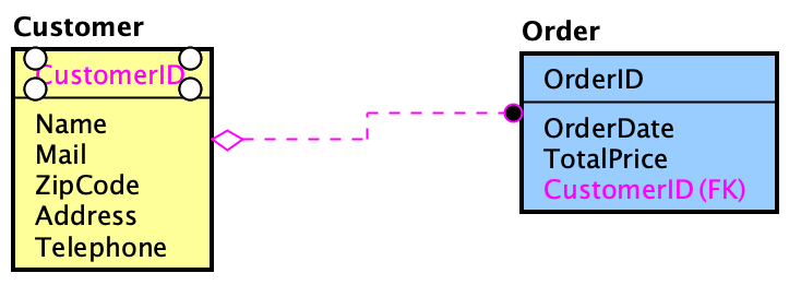
Relationships
You can create relationships using the Tool Palette. Select the desired relationship type and click the two Entities you wish to connect.
Available Relationship Types
IDEF1X | IE | Relationship type |
|---|---|---|
| Identifying Relationship | ||
| Non-Identifying Relationship | ||
| Many-to-many Relationship |
- Hover one ER Entity first to reveal a mini icon. Click it and select a relationship type from it.
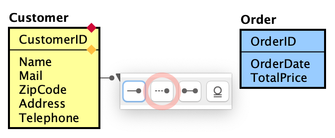
- Click the second ER Entity.
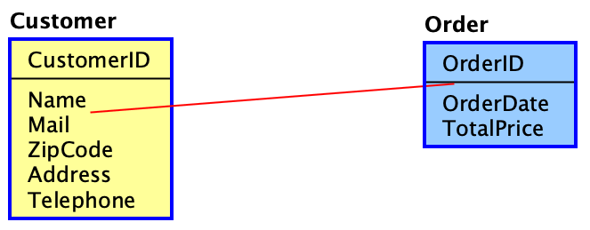
- The relationship is created, and Foreign keys are automatically generated based on the relationship type.
SQL Export
You can export ER Entities into SQL (SQL-92).
- Go to [Tools] > [ER Diagram] > [Export sql].
- In the dialog that opens, specify which models to export, export location and click [Export].
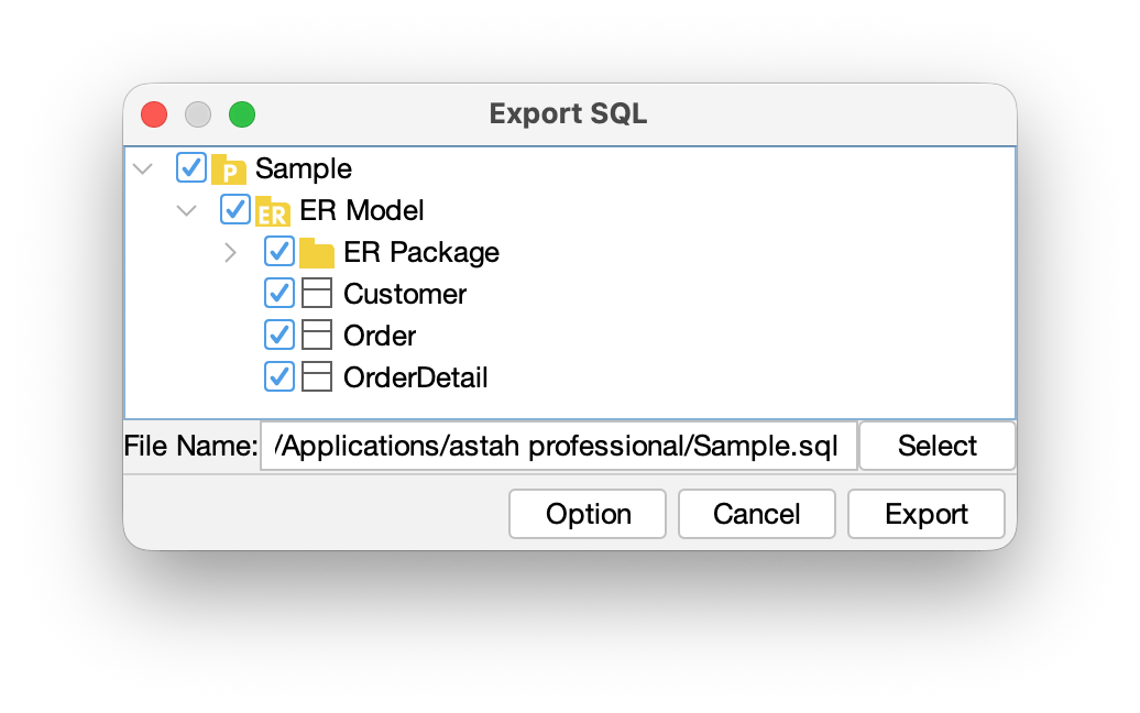
- In the [Option], you can specify more detailed settings.
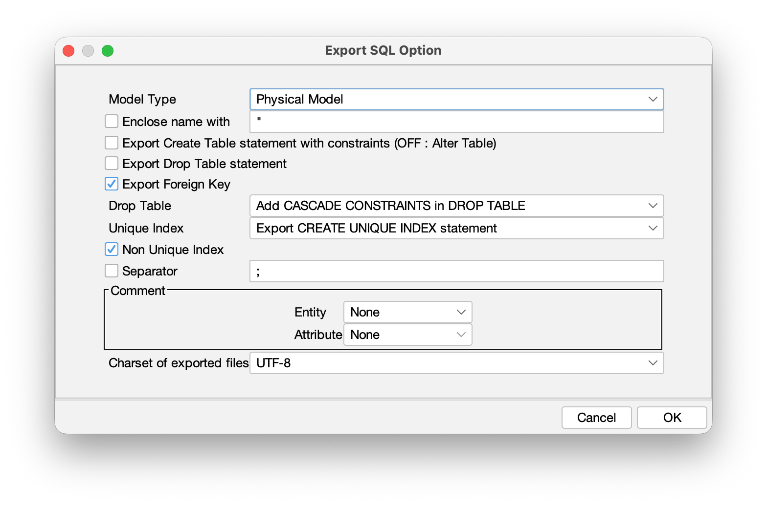
TIPS: Export Entity Definition as a comment
You can export the Entity’s definition as a comment by configuring so in the [Option] menu.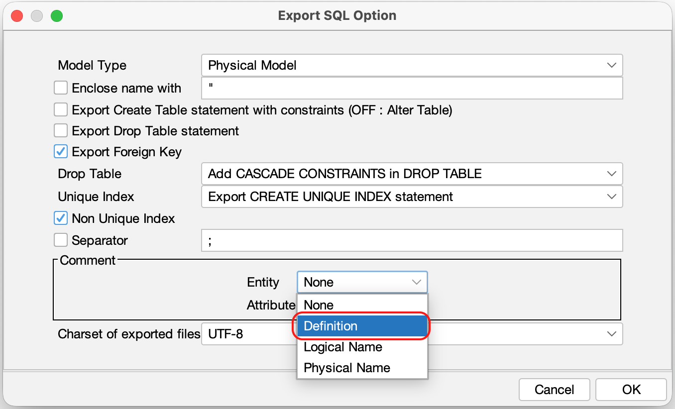
Managing ER Data Types
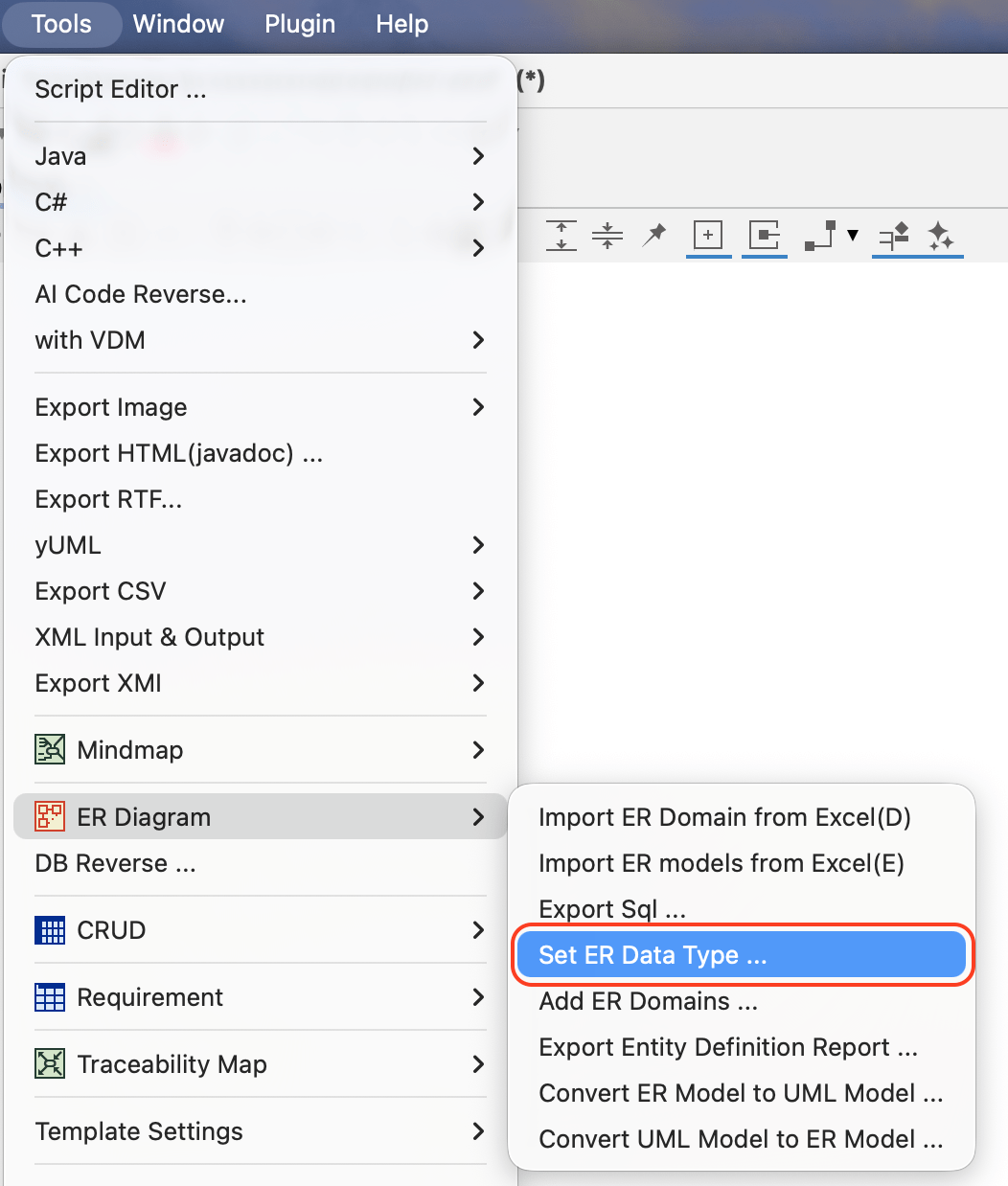
- Go to [Tools] – [ER Diagram] – [Set ER Data Type] from main menu.
- Click the [Add] button to create a new data type.
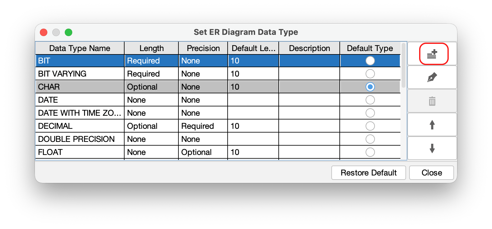
- Enter the Name and parameters for the data type, then click [OK].
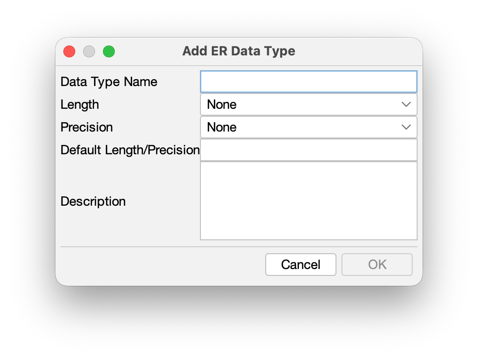
TIPS: To set a specific data type as the default for new Attributes, check the [Default Type] box when creating or editing it.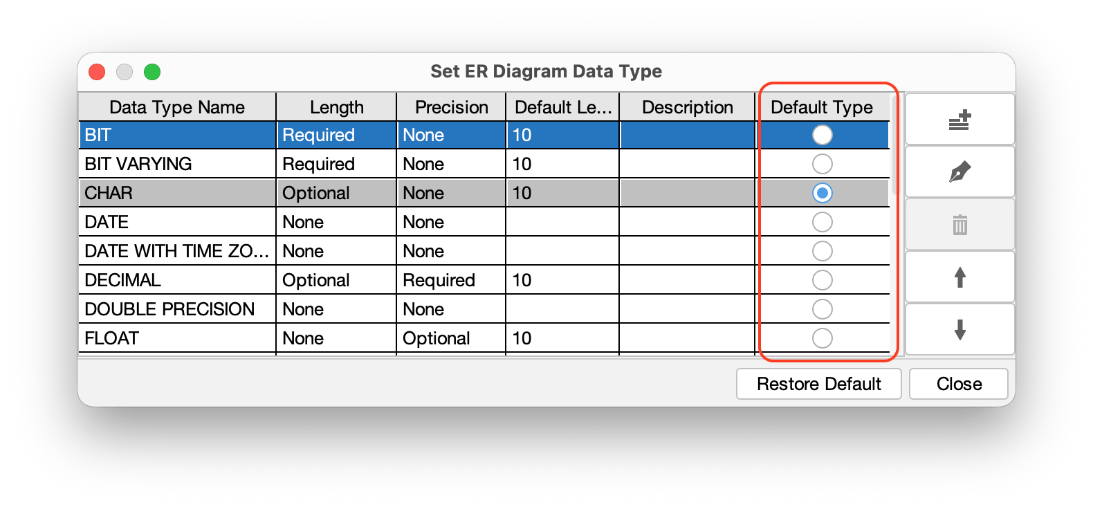
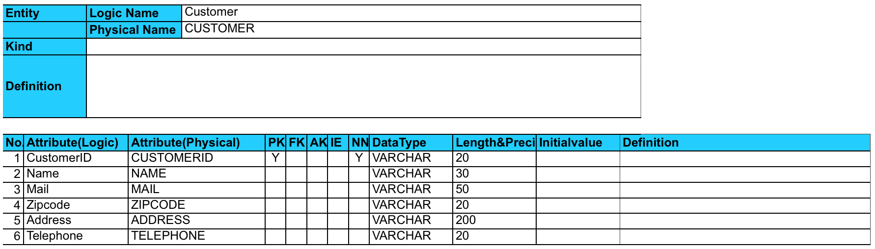
Export Entity Definition Report
You can export a comprehensive list of ER Domains, Entities and detailed Entity information to an excel file.
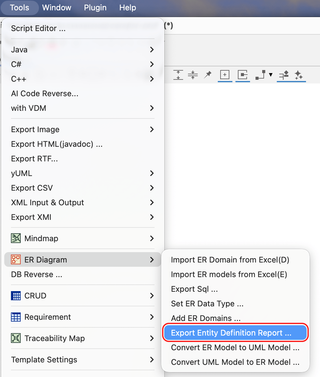
1. Go to [Tools] – [ER Diagram] – [Export Entity Definition Report].
2. Check models you want to include in the report, then specify the save location and file name. Click [Export] to generate the Excel file.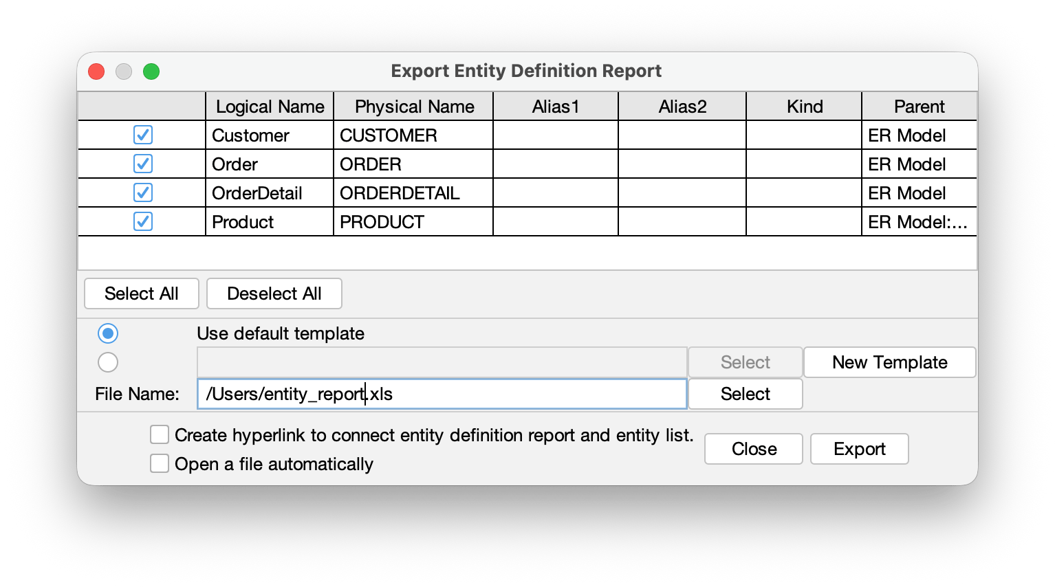
Export format of Attributes and its TaggedValues
| Logical Name of Attribute | $each.entity.each.attribute.logical_name |
|---|---|
| Physical Name of Attribute | $each.entity.each.attribute.physical_name |
| Domain Name of Attribute | $each.entity.each.attribute.domain |
| Primary Key Flag of Attribute | $each.entity.each.attribute.pk |
| Foreign Key Flag of Attribute | $each.entity.each.attribute.fk |
| NotNull Flag of Attribute | $each.entity.each.attribute.notnull |
| Reference of Attribute | $each.entity.each.attribute.ref |
| Datatype of Attribute | $each.entity.each.attribute.type |
| Length/Precision of Attribute | $each.entity.each.attribute.length_precision |
| Initial Value of Attribute | $each.entity.each.attribute.initial_value |
| TaggedValue of Attribute | $each.entity.each.attribute.initial_value |