Creating Objects
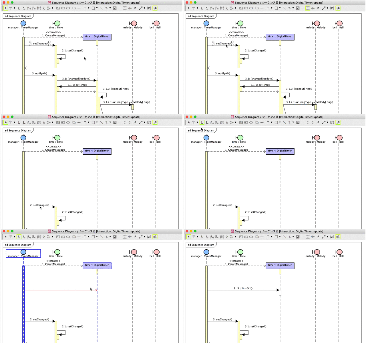
Before you start, learn basic operations to create objects and lines. There are 5 ways to create model elements.
1. Using a tool palette
Choose an icon you want to create from the tool palette then click on a diagram.
2. Drag from tree
Drag a model from the tree and drop it on a diagram.
3. Using a Suggest Feature
Click a mini icon that appears when you have a mouse over an object.
If you want to hide these mini icons, click an object or hold [Shift] key down.
4. Double-clicking on the diagram
Directly double-clicking on the diagram creates the following model elements.
Diagram | Model |
|---|---|
| Class Diagram | Class |
| UseCase Diagram | UseCase |
| Statemachine Diagram | State |
| Activity Diagram | Action |
| Sequence Diagram | Lifeline |
| Communication Diagram | Lifeline |
| Component Diagram | Component |
| Composite Structure Diagram | Structured Class |
| Flowchart | Process |
| Data Flow Diagram | Process Box |
| ER Diagram | ER Entity |
| Mind Map | Root Topic |
| Requirement Diagram | Requirement |
5. Pasting texts from Clipboard
You can create models by simply pasting texts on a diagram.
Since version 8.5, you are able to add Attributes and Operations to a Class by pasting texts and also add ER Attributes to ER Entity.

Create objects in a row
There are two ways to create the same model element continuously.
- Hold [Shift Key] down
Keep clicking on a diagram with holding the [Shift] key down. - Turn on the [Continuous] mode
Click the [Continuous] mode on the tool palette.

Wrap text
You can wrap text with [SHIFT+ENTER], [ALT+ENTER] or [CTRL+ ENTER].
However, you cannot wrap the text for some models.

Specify color
You can specify colors for diagram elements including line elements. There are two ways to do so:
From Toolbar
Before you create diagram elements, choose a color you want to use then create diagram elements.
(You can also change colors for existing diagram elements.)
By selecting [Set Color] option, you can call detailed color choosers/palettes.
There are two palettes you can switch between [Custom] and [Swatches].


Also, enabling [Apply to Created Elements] option maintains the color selection, so that the diagram elements you will create stay in the selected color until you turn it off.

From [System Properties]
You can configure default color for each diagram element type. To do so, go to [Tools] – [System Properties] – [Default Item Color]. Then select color and click [Apply] – [OK].
NOTE:
- Enabling [Apply to Created Elements] on takes precedence over the default color specified in the [Tools] – [System Properties] – [Default Item Color].
TIPS: Set default size of model elements
You can set default size for all the model elements in the [Tool] – [System Properties] – [Default Item Size].

Expand and reduce space
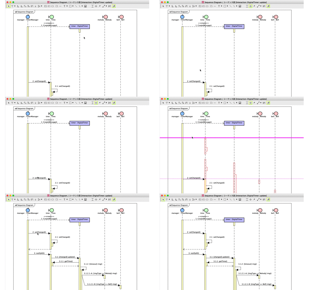
When you want to expand the space before you insert objects or reduce space to make a better diagram appearance, use this [Gap expander/remove] tool.
Expand the space

Reduce the space
