Quick SysML Diagram Tutorial With Astah
- UseCase Diagram
Now let’s create the following UseCase Diagram. This UseCase Diagram is the same as “Figure D.6 – Establishing Operational Use Cases for “Drive the Vehicle” (Use Case Diagram)” in the SysML 1.5 specification.

Add UseCase Diagram
- If this is where you are starting this tutorial, you can download the project file that includes all the Block Definition Diagram, Internal Block Diagram and Parametric Diagram that were made throughout this tutorial. Also, please download Astah SysML.
- Open the file, right-click on the “parametricDomain” package and click [Create Diagram] – [UseCase Diagram].
- Then a blank UseCase diagram will be added and displayed in the Diagram Editor.

Create UseCases and Actors
You can click on the “Actor” button and then click on the diagram to place an actor.
Type the name “Driver” and press Enter.

Next, select the “Use Case” button to create 6 UseCases.
Rename them “Drive the vehicle”, “Start the vehicle”, “Accelerate”, “Steer”, “Park” and “Brake”.


TIPS(1)
You can create UseCases by double-clicking on the diagram without selecting “UseCase” on the tool palette.

TIPS(2)
You can also create UseCases by copy and paste of UseCase names!

Align and adjust sizes of objects
At this point, you may want to tweak the UseCases sizes and align them nicely for a better-looking diagram.
To do so, use [Alignment] menu. In this demo, all the UseCase sizes are cloned by using [Alignment] – [Adjust Size] menu then relocate the UseCases by using [Alignment] – [Align Vertically] – [Space Evenly Vertically].

Associations between Actor and UseCases
There are several types of lines that you can create between Actors and UseCases.
Let’s create association first.
You can choose the type of lines you want to create on the tool palette and click Actor then UseCase.
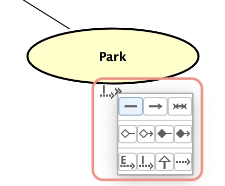
Or alternatively, you can have your mouse over an object then choose the line type, then directly click the target model.
After creating associations, create “include” and “exclude” in the same way.
You can download the file that contains this UseCase Diagram from here.