
Quick SysML Diagram Tutorial With Astah
- Parametric Diagram

Add a Parametric Diagram
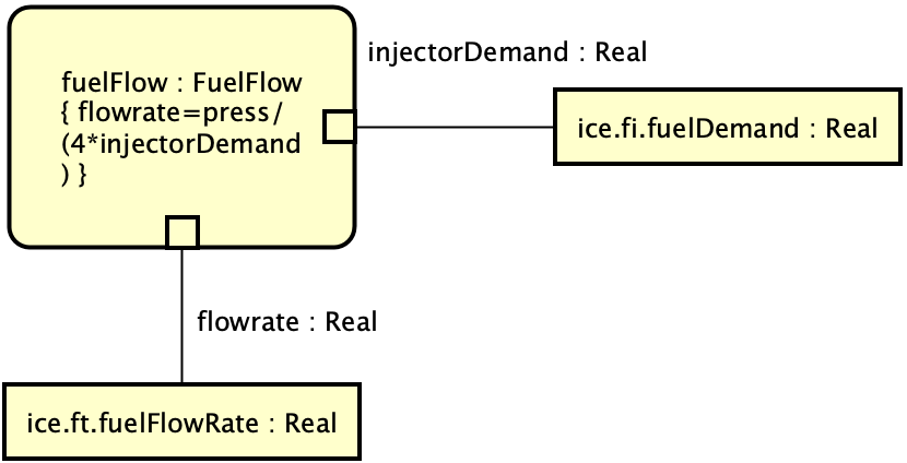
Let’s draw the following parametric diagram. This parametric diagram is taken from Figure D.24 – Defining Fuel Flow Constraints (Parametric Diagram) of the SysML 1.5 specification.

1. Add a Parametric Diagram to “PowerSubSystem” Block
- Open “PowerSubsystem Fuel Flow Definition Diagram.
If you are starting the tutorial from this page, download Astah SysML and the sample file. - Right-click on the “PowerSubsystem” block and select “Add Parametric Diagram” from the pop-up menu.
TIPS! Use [Search] pane when you look for a specific model! - Then a Parametric Diagram will open.
Parametric Diagram may look similar to the Internal Block Diagram we have been drawing.
A Parametric Diagram is actually a restricted Internal Block Diagram.
Therefore, you can create Parametric Diagrams in the same way as Internal Block Diagrams.
You can create Constraint Properties as parts of the Internal Block Diagram and Constraint Parameters as Ports. However, the type of Constraint Properties is restricted to Constraint Blocks.
Now let’s create “fuelFlow:FuelFlow” Constraint Properties!
Create Constraint Property
Constraint Properties express the constraints of a constraint block of type.
- Create a “ParametricDomain” package from the pop-up menu of the project root in the structure tree.
- Create a “FuelFlow” Constraint Block from the pop-up menu of the “ParametricDomain” package.
- In the Constraints tab of the Properties View, press “Add” and enter “flowrate=press/(4*injectorDemand)” in the Constraints edit area.
- Drag and drop the “FuelFlow” constraint block from the structure tree onto the Parametric Diagram and rename it to “fuelFlow”.
Add Value Properties
Let’s create the “ice.fi.fuelDemand” value property.
First, we need to ask you to modify the “PowerSubsystem Fuel Flow Definition” Block Definition Diagram as shown below.

Or you can download the file that contains this Block Definition Diagram. (Diagram Name: PowerSubsystem Fuel Flow Definition – after)
- Click “Value Property” tool button on the tool palette.

- Click on the diagram to open the “Add Property” dialog.
- Expand the “ice:InternalCombustionEngine” part.
- Select “fuelDemand:Real” in the “fi:FuelDemand” part on the part hierarchy and press OK.
- Then “ice.fi.fuelDemand” value property will appear on the diagram.
- Do the same and select “fuelFlowRate:Real” to create another.
Constraint Parameter
- Click the “Constraint Parameters” and click the “fuelflow : FuelFlow” constraint property.

- Change the constraint parameter name to “injectorDemand”.
- Add the constraint parameter “flowrate” in the same way.
Binding Connector
Now let’s use the Binding Connector to connect the value property and the constraint parameter.
- Select [Binding Connector] from tool palette
- Select the “ice.fi.fuelDemand” value property and click on the “injectorDemand:Real” constraint parameter.
- Connect the “ice.fi.fuelFlowRate” value property and the “flowrate:Real” constraint parameter in the same way.
You can download the file that contains this Parametric Diagram from here.