
Quick SysML Diagram Tutorial With Astah
- Internal Block Diagram


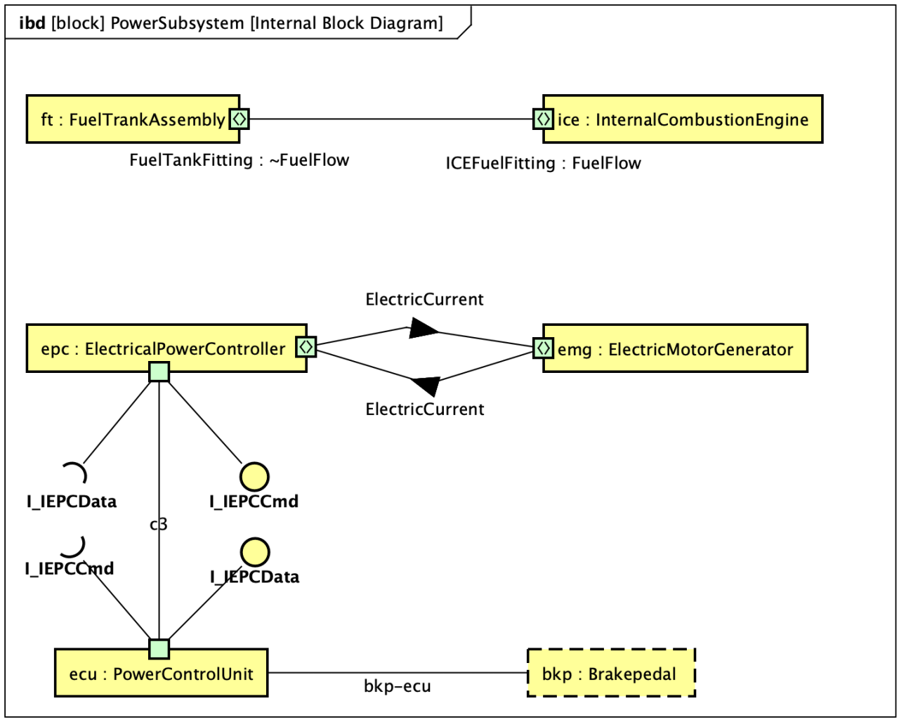
You have created two block definition diagrams. Now let’s move on to the Internal Block Diagram. The diagram you are going to create is an excerpt from “Figure D.19 – Internal Structure of the Power Subsystem (Internal Block Diagram)” of the SysML 1.5 specification, with a few additional parts.

Add a new Internal Block Diagram
If you are starting from here, download the Astah SysML trial and the sample file with the two BDDs.
- Open the “PowerSubsystem Fuel Flow Definition” block definition diagram.
- Right-click the “PowerSubsystem” block and select [Add Internal Block Diagram] from the pop-up menu.

The internal block diagram is added and opens in the Diagram Editor. The “FuelTankAssembly” block and the other blocks connected by composition are placed as part properties, and their association end names, such as “ft”, become the part property names.
Add New Part Properties
- Click the [Part Properties/Reference Properties] button on the tool palette, then click on the diagram.

- In the [Add Property] dialog, enter “epc: ElectricalPowerController” and click [OK]. This names the part “epc” and sets “ElectricalPowerController” as its type.
- Because the “ElectricalPowerController” block does not exist in the project yet, you are asked whether to create it. Click [Yes].
Create the “emg: ElectricMotorGenerator” and “ecu: PowerControlUnit” parts in the same way.
Add a Reference Property
Let’s add a reference property by drag and drop.
- Right-click the project root in the Structure Tree, select [Create Model] – [Block], and name the new block “BrakePedal”.
- Drag the “BrakePedal” block from the Structure Tree onto the internal block diagram.
- In the [Model Type] dialog, choose [Reference Property] and click [OK].
Add Ports
Add an “I_IEPC” port to the “epc: ElectricalPowerController” part.
- Click the [Port] button on the tool palette, then click the bottom edge of the “epc: ElectricalPowerController” part.
- In the [Base] tab of the port’s Property View, set the port name to “I_IEPC” and its type to the “FuelFlow” block.
Then add ports to the other two parts:
- Add a port to “emg: ElectricMotorGenerator” and set its type to “FuelFlow”.
- Add a port to “ecu: PowerControlUnit”.
- Hide the port names and types from each port’s pop-up menu.
Add Item Flows
To add an item flow, select the [Item Flow] tool button, then click two ports. The port you click first becomes the source of the item flow.

- Click the port of the “epc: ElectricalPowerController” part, then the port of the “emg: ElectricMotorGenerator” part.
- Create a second item flow in the opposite direction in the same way.
Convey
Let’s add a conveyed item to the item flow you created.
- Right-click the project root in the Structure Tree, select [Create Model] – [Block], enter “ElectricCurrent” and press Enter.
- Select the item flow. In its Property View, click the empty space under [Convey] and select the “ElectricCurrent” block.
Interface
Now let’s add a required interface and a provided interface to the “I_IEPC” port of the “epc: ElectricalPowerController” part.
- First, add another “I_IEPC” port to the “epc: ElectricalPowerController” part.
- Click the [Interface] tool button and place an interface to the lower left of the “I_IEPC” port of the “epc: ElectricalPowerController” part.

- Enter “I_IEPCData” as the interface name.
- Click the [Usage Dependency] button, then the “I_IEPC” port, then the “I_IEPCData” interface.

- You are asked how to set the port type. Select [Use existing model] and choose “PowerControlUnit”. The interface becomes a required interface.
- Click the [Interface] tool button again, then click to the right of the interface you just created. Enter “I_IEPCCmd” as the interface name.
- Click the [Realization] tool button, then the “I_IEPC” port, then the “I_IEPCCmd” interface. The interface becomes a provided interface.

In the same way, add a required interface and a provided interface to the port of the “ecu: PowerControlUnit” part.
- Click the [Required Interface] tool button, click near “I_IEPCData”, then click the port of the “ecu: PowerControlUnit” part.

- Select [Use existing model] and specify “ElectricalPowerController”.
- In the next dialog, select [Use existing model] again and specify the “I_IEPCCmd” interface.
- For the provided interface, click the [Provided Interface] tool button, click near “I_IEPCCmd”, then click the port of the “ecu: PowerControlUnit” part.

- Select [Use existing model] and specify the “I_IEPCData” interface.
Connector
Finally, create connectors. Select [Connector] on the tool palette, then click the “FuelTankFitting: FuelFlow” port and then the “ICEFuelFitting: FuelFlow” port.

In the same way, create a connector between the ports of the “epc: ElectricalPowerController” and “ecu: PowerControlUnit” parts, and another between “ecu: PowerControlUnit” and “bkp: BrakePedal”.
You can download the file that contains this internal block diagram.